 by
Mass concrete mix design involves selecting concrete ingredients and construction controls that satisfy strength, durability and workability requirements while managing heat generated during hydration.
In thick rafts, large pile caps, bridge foundations and similar elements, heat can accumulate inside the concrete. Temperature differences and restrained contraction during cooling can then produce tensile stresses and thermal cracks.
A mix that achieves the required cube strength is therefore not automatically suitable for a massive concrete placement. Its heat-development characteristics must be considered alongside placing temperature, construction sequence, curing, insulation and temperature monitoring.
This guide explains the principles, material selection, thermal verification, practical calculations and site controls involved in mass concrete construction.
For the complete learning sequence, visit our Concrete Mix Design Hub.
Page Contents
Quick Information About Mass Concrete Mix Design
| Item | Practical guidance |
|---|---|
| Main objective | Achieve strength, durability and constructability with appropriate thermal control |
| Typical applications | Thick rafts, large pile caps, bridge foundations, machine foundations and dams |
| Main source of internal heat | Hydration of cementitious materials |
| Main cracking mechanism | Restrained thermal movement exceeding the developing concrete capacity |
| Definition by thickness | No single thickness identifies every mass-concrete situation |
| Binder selection | Consider heat development, strength, durability and construction schedule together |
| SCMs | Suitable fly ash and GGBS combinations may improve thermal performance |
| Temperature criteria | Establish placing, peak, differential and cooling-rate requirements separately |
| Verification | Material testing, mix trials and applicable thermal assessment |
| Monitoring | Follow the approved sensor layout, recording interval and response procedure |
| Examples in this article | Illustrative calculations, not approved site mixes or reported project results |
What Is Mass Concrete?
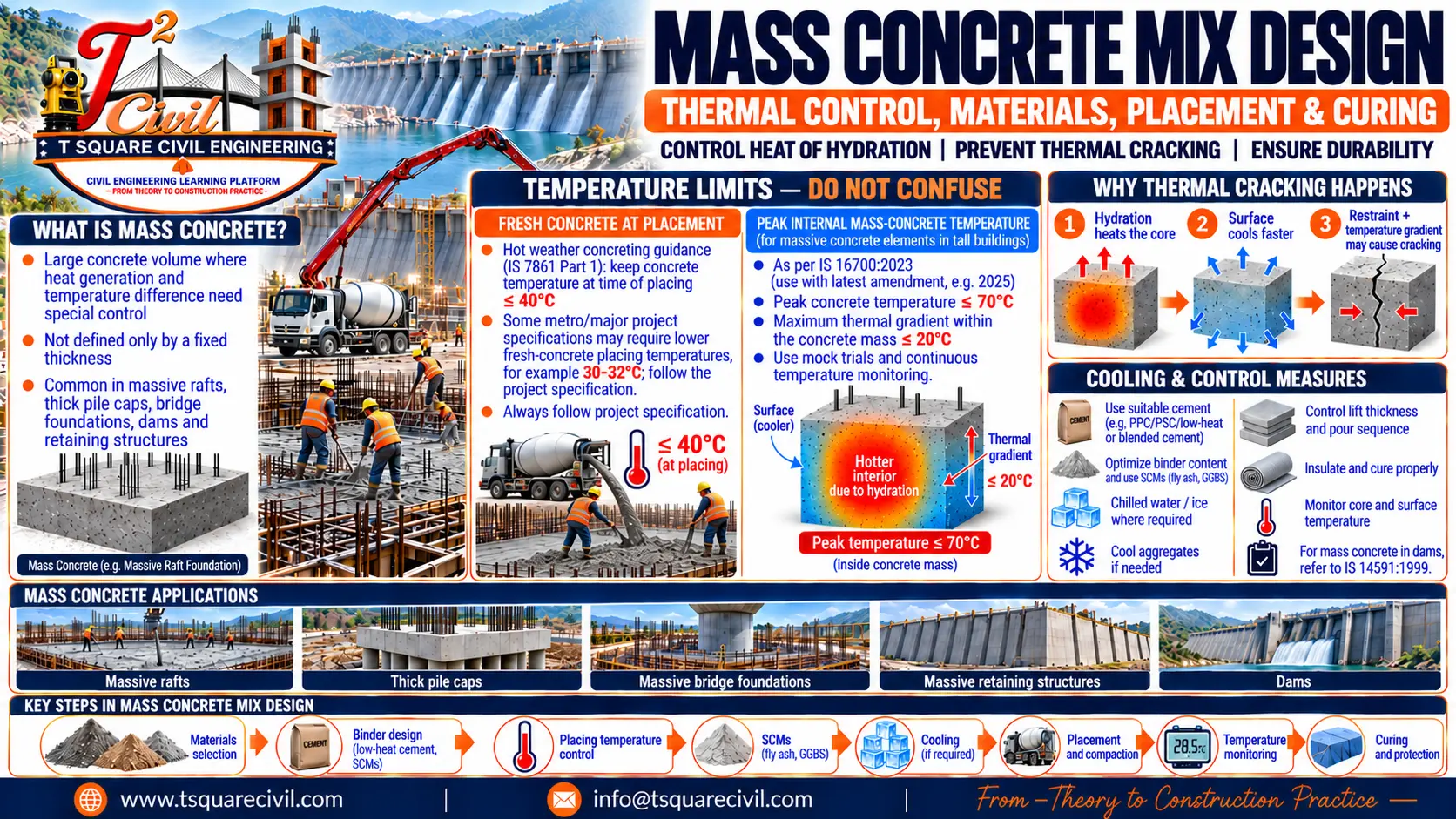
Mass concrete is concrete in which the combination of member dimensions, mixture characteristics and surrounding conditions makes hydration heat and its consequences important to design and construction.
The term is not limited to dams or unreinforced concrete.
A reinforced raft, pile cap or thick wall may require mass-concrete thermal controls when its interior retains sufficient heat to create adverse temperature conditions.
The assessment should consider:
- Member dimensions and geometry.
- Cementitious-material type and quantity.
- Rate of heat development.
- Concrete placing temperature.
- Ambient conditions.
- Formwork and insulation.
- Restraint from foundations or adjoining construction.
- Lift arrangement and placement sequence.
Practical takeaway: Assess the expected temperature history and restraint conditions instead of deciding only from member thickness.
Mass Concrete and Hot-Weather Concreting Are Different
Hot-weather precautions address the effects of environmental conditions on concrete production, placement and curing.
Mass-concrete thermal control addresses heat retained within a substantial concrete element and the stresses associated with temperature differences and restrained cooling.
Both conditions can occur during the same pour. However, mass concrete may also require thermal control during cool weather.
| Aspect | Mass concrete | Hot-weather concreting |
|---|---|---|
| Main concern | Retained hydration heat and restrained thermal movement | Environmental effects on fresh concrete and early curing |
| Typical controls | Binder optimization, thermal assessment, insulation, monitoring and controlled cooling | Material cooling, delivery coordination, workability retention and curing |
| Important measurements | Internal temperature history, simultaneous temperature differences and cooling rate | Material temperature, fresh-concrete temperature and relevant weather conditions |
| Can occur in cool weather? | Yes | Depends on the environmental conditions affecting the work |
For environmental precautions, refer to Hot Weather Concrete Mix Design.
Where Is Mass Concrete Used?
| Application | Important thermal consideration |
|---|---|
| Thick raft foundations | Interior heat accumulation and restraint at the foundation interface |
| Large pile caps | Member thickness, reinforcement congestion and placement conditions |
| Bridge foundations | Large dimensions, construction joints and external restraint |
| Machine foundations | Block geometry, embedded items and loading requirements |
| Concrete dams | Lift sequence, foundation restraint and long-term cooling |
| Thick walls and transfer elements | Section geometry and restraint from adjoining construction |
| Large industrial pedestals | Heat development and construction loading schedule |
The approved design and project specification should establish the thermal requirements for each element.
Heat of Hydration in Mass Concrete
Hydration is the reaction between cementitious materials and water. It releases heat.
In a relatively thin member, heat can escape more readily to the surroundings. In a massive element, the surrounding concrete slows heat loss from the interior.
Consequently, the interior may become considerably warmer than the surface.
| Factor | Influence on temperature development |
|---|---|
| Cement composition and fineness | Affect the rate and amount of heat release |
| Cement quantity | Affects the quantity of heat-generating material |
| SCM type and proportion | Change heat and strength development |
| Initial concrete temperature | Influences hydration rate and starting temperature |
| Member dimensions | Affect the distance through which heat must escape |
| Formwork and insulation | Change heat exchange with the surroundings |
| Lift sequence | Changes the thermal conditions of successive placements |
Both the rate of heat release and the total heat released matter.
A slower heat-development system may reduce or delay the peak temperature, but its actual performance depends on the complete mix and placement conditions.

Why Thermal Cracking Occurs
Temperature-related movement creates stress when that movement is restrained.
Internal Restraint
Different parts of the same element may attempt to expand or contract by different amounts.
For example, the surface may cool and contract while the interior remains hotter. Restraint from the interior can produce tensile stress near the surface.
Surface cracking can therefore develop before the entire concrete mass has cooled.
External Restraint
Foundation rock, earlier concrete placements or adjoining structural elements can restrict contraction as the new concrete cools.
This may produce tensile stress through a substantial part of the section.
Cracking becomes possible when the induced tensile stress or restrained strain exceeds the concrete’s developing capacity.
The response depends on temperature history, thermal expansion, tensile strength, stiffness, creep, geometry and restraint.
Reinforcement can help control crack distribution and width, but it does not replace thermal control.
Placing Temperature, Peak Temperature and Temperature Difference
These parameters describe different conditions and should be recorded separately.
| Parameter | Meaning | Purpose |
|---|---|---|
| Placing temperature | Temperature of fresh concrete at placement | Delivery and precooling acceptance |
| Peak internal temperature | Highest temperature reached inside the concrete after placement | Heat-development assessment |
| Internal temperature difference | Difference between specified locations at the same time | Assessment of non-uniform heating and cooling |
| Cooling rate | Temperature reduction over a defined period | Assessment of cooling behaviour |
| Ambient temperature | Temperature of the surrounding air | Environmental and boundary-condition assessment |
A 70°C internal peak limit does not permit fresh concrete to be placed at 70°C.
Fresh-Concrete Placing Temperature
IS 7861 (Part 1):1975, Clauses 6.1 and 7.1, calls for concrete temperature below 40°C at placement for hot-weather concreting.
A mass-concrete thermal design or project specification may require a substantially lower value.
For example, where a Metro project specifies a maximum placing temperature of 30°C or 32°C, that particular requirement governs. These values should not be presented as universal limits for every Metro project.
Temperature Criteria in IS 16700
For the massive elements addressed by IS 16700:2023, Annex C, C-1(h), the stated criteria include:
- Maximum peak concrete temperature of 70°C.
- Maximum temperature difference within the concrete mass of 20°C.
- Appropriately designed mock trials before actual concreting.
- Continuous temperature recording using an adequate number of sensors.
These provisions belong to the standard’s tall-building context and should not automatically be transferred to every dam, bridge or industrial foundation.
The thermal-control plan should identify the governing criteria, sensor locations, alarm levels, response procedure and conditions for ending monitoring.
Meeting a temperature-difference limit alone does not demonstrate that externally restrained cooling cannot cause cracking.
Relevant Indian Standards
| Standard | Relevance |
|---|---|
| IS 10262:2019 | Concrete mix proportioning |
| IS 456 | Structural-concrete and durability provisions, where applicable |
| IS 7861 (Part 1):1975 | Hot-weather concreting precautions |
| IS 16700:2023 | Requirements for tall concrete buildings within its scope |
| IS 14591:1999 | Temperature control of mass concrete for dams |
| IS 12600:1989 | Low Heat Portland Cement specification |
IS 14591 primarily addresses precooling for dam mass concrete and also discusses post-cooling. Apply its guidance with attention to that scope.
Use the editions and amendments applicable to the project. Mix-proportioning calculations do not replace thermal verification.
Information Required Before Mix Design
| Category | Information to establish |
|---|---|
| Structural requirements | Grade, target mean strength, acceptance age and loading schedule |
| Durability | Exposure, permissible water ratio and applicable binder-content requirements |
| Geometry | Member dimensions, construction joints and lift arrangement |
| Restraint | Foundation conditions and connections to existing construction |
| Materials | Cement, SCM, aggregate, water and admixture properties |
| Workability | Required slump, retention period, transport time and placing method |
| Thermal requirements | Placing temperature, peak temperature, temperature difference and cooling criteria |
| Construction controls | Pour sequence, curing, insulation and formwork removal |
| Monitoring | Sensor layout, logging arrangements, alarms and responsible personnel |
For the general calculation sequence, see Concrete Mix Design Procedure as per IS 10262:2019.
Selecting Cement and SCMs for Thermal Performance
The cementitious system should satisfy strength and durability requirements while providing a suitable heat-development profile.
| Material or approach | Potential contribution | Main checks |
|---|---|---|
| Low Heat Portland Cement | Controlled heat development | Availability, strength development and project suitability |
| Fly ash | Reduced early heat contribution in suitable mixtures | Material quality, setting, early strength, curing and thermal behaviour |
| GGBS | Suitable heat and durability performance | Replacement level, fineness, temperature sensitivity and strength development |
| Silica fume | Strength and permeability performance | Water demand, viscosity, admixture demand and complete-system thermal behaviour |
| Reduced unnecessary binder | Lower quantity of heat-generating material | Strength, durability, paste demand and pumpability |
The maximum permitted replacement percentage is not automatically the optimum percentage for mass concrete.
A slower strength-development profile must suit lift intervals, formwork removal, construction loading and curing arrangements.
Silica fume is not automatically a heat-reduction material. Where it is needed for other performance requirements, assess its contribution within the complete binder system.
When blended cement is used, account for its constituents appropriately and avoid counting the same SCM twice.
For material properties and replacement calculations, see Fly Ash, GGBS and Silica Fume in Concrete Mix Design.
Water and Binder Optimization
Select the water ratio to satisfy strength and durability requirements.
For preliminary calculation:
Total binder content = Effective free water ÷ Selected w/cm
Check the calculated quantity against applicable content limits, permitted SCM use, workability and trial performance.
Do not assume that every powder or filler qualifies as cementitious material for durability compliance.
Suitable aggregate grading and a compatible water-reducing admixture may reduce water demand and allow a lower binder content at the same w/cm.
However, excessive paste reduction can create a harsh mixture or pumping difficulty.
Practical Example: Reducing Binder Demand
Assume:
- Selected w/cm = 0.45
- Initial effective free water = 180 kg/m³
Initial binder demand:
180 ÷ 0.45 = 400 kg/m³
Suppose trials demonstrate that improved grading and a suitable admixture reduce water demand to 162 kg/m³ at the required workability.
Revised binder demand:
162 ÷ 0.45 = 360 kg/m³
Calculated reduction:
400 − 360 = 40 kg/m³
For an illustrative 70% OPC and 30% fly ash combination:
| Constituent | Initial trial | Revised trial |
|---|---|---|
| Effective free water | 180 kg/m³ | 162 kg/m³ |
| OPC | 280 kg/m³ | 252 kg/m³ |
| Fly ash | 120 kg/m³ | 108 kg/m³ |
| Total binder | 400 kg/m³ | 360 kg/m³ |
| w/cm | 0.45 | 0.45 |
For a 1,000 m³ pour:
Calculated binder reduction = 40 × 1,000 = 40,000 kg = 40 tonnes
This demonstrates the arithmetic, not an approved production mix.
Equal w/cm does not guarantee equal strength or pumpability. Aggregate quantities must be recalculated, and all applicable content requirements must be satisfied.
A 10% binder reduction does not establish a 10% reduction in peak concrete temperature.
Aggregate and Admixture Selection
Larger suitable aggregate and good combined grading can reduce water and paste demand.
However, mass concrete does not automatically require 40 mm aggregate. The selected size must suit reinforcement spacing, cover, geometry, pumping and compaction access.
The admixture should be evaluated with the actual cementitious system at representative temperatures. Check water reduction, slump retention, stability, setting and strength development.
When the binder system changes, recalculate constituent volumes and aggregate quantities using the Absolute Volume Method.
Precooling, Insulation and Post-Cooling
Different thermal-control measures act at different stages.
| Measure | Role | Important limitation |
|---|---|---|
| Shaded or cooled aggregates | Reduces initial heat entering the batch | Cooling water can change aggregate moisture |
| Chilled mixing water | Reduces initial concrete temperature | Hot aggregates may still dominate the heat balance |
| Ice replacement | Absorbs heat during melting and warming | Ice must be included in total water and melt during mixing |
| Delivery coordination | Limits avoidable temperature change and waiting | Temperature must still be checked at the specified acceptance point |
| Insulation | Slows surface cooling | Can retain internal heat |
| Embedded cooling pipes | Removes heat after placement | Requires designed layout and controlled operation |
Precooling reduces the starting temperature. It does not eliminate subsequent hydration heat.
The practical 70% ice-replacement guidance discussed in IS 14591 belongs to its dam-concrete context and should not be treated as a universal dosage for structural concrete.
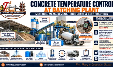
For detailed plant methods, refer to Concrete Temperature Control at Batching Plant.
Practical Example: Ice and Moisture Correction
Assume these quantities per cubic metre:
| Item | Quantity |
|---|---|
| Design effective free water | 160 kg |
| Ice expressed as melted-water mass | 50 kg |
| Aggregate free moisture above SSD | 20 kg |
| Water contributed by liquid admixture | 2 kg |
Assume there is no absorption deficit.
Required liquid batch water:
160 − 50 − 20 − 2 = 88 kg/m³
Water-balance check:
88 + 50 + 20 + 2 = 160 kg/m³
If the operator deducts only the ice and adds 110 kg/m³ of liquid water:
Actual effective free water = 110 + 50 + 20 + 2 = 182 kg/m³
For a binder content of 400 kg/m³:
| Condition | Calculation | w/cm |
|---|---|---|
| Intended | 160 ÷ 400 | 0.400 |
| Incorrect batching | 182 ÷ 400 | 0.455 |
Aggregate wet batch masses must also be corrected to maintain the intended aggregate solids. Where aggregates are below SSD, account for absorption using the approved procedure.
For the underlying calculations, see Moisture Correction in Concrete Mix Design.
Mass Concrete Trial and Thermal Verification Procedure
Establish the Trial Programme
Define the candidate mixtures, performance requirements and comparison criteria.
The programme should consider strength, durability, workability, heat development and construction timing together.
Verify Routine Concrete Performance
Use representative production materials and correct the batch quantities for actual moisture.
Check workability, retention, stability, fresh density, yield and strength at the specified ages. Include setting or other tests where required.
The general laboratory process is explained in Concrete Trial Mix Procedure.
Characterize Heat Development
Where required, use adiabatic or semi-adiabatic testing and other approved methods to establish the heat-development characteristics of the candidate mixes.
The thermal assessment may also require material properties such as thermal conductivity, specific heat and thermal expansion.
The project’s responsible engineer should define the required testing programme.
Assess the Actual Element
Evaluate the intended member using representative:
- Geometry and boundary conditions.
- Placing temperature.
- Binder heat development.
- Lift dimensions and timing.
- Formwork and insulation.
- Ambient conditions.
- Restraint assumptions.
A favourable laboratory strength result does not demonstrate that the element will satisfy thermal criteria.
Conduct Instrumented Mock Trials Where Required
Instrumented trials help assess the combined mix and construction method.
A small trial block does not automatically reproduce a much larger raft because its heat-loss conditions differ.
Where the cited IS 16700 provision applies, conduct the required mock trials and monitoring.
Approve the Mix and Thermal-Control Plan
Approval should address the proportions, material sources, production controls, construction method, monitoring arrangement and response procedure.
A significant change in binder source, proportions or placement conditions may require reassessment.
Lift Arrangement and Construction Sequence
Lift thickness, placement size and the interval between lifts influence heat dissipation and restraint.
Previously placed concrete may affect both the temperature and movement of a subsequent lift.
The construction sequence should therefore be assessed together with the thermal design.
Do not divide a structural pour into smaller lifts or introduce additional construction joints solely as an informal cooling measure. Joint locations and sequencing must remain consistent with the approved structural and construction requirements.
Temperature Monitoring and Interpretation
Locate sensors according to the approved plan.
Positions may include the expected hottest zone, near-surface regions, corners, intermediate depths and construction interfaces.
Record sensor identification and position, and check operation before placement.
Calculate temperature differences using readings taken at the same time.
A surface minimum recorded at night and a core maximum recorded earlier do not form a valid simultaneous temperature difference.
Practical Example: Acceptable Core Reading but Excessive Difference
Assume the approved criteria for an illustrative placement are:
- Maximum peak temperature: 70°C
- Maximum core-to-near-surface difference: 20°C
At one recording time:
| Measurement | Reading |
|---|---|
| Core temperature | 62°C |
| Near-surface temperature | 40°C |
| Simultaneous difference | 22°C |
Calculation:
62 − 40 = 22°C
The core reading is below the assumed peak limit, but the difference exceeds the assumed differential limit by 2°C.
Verify the readings and follow the approved response procedure.
Suddenly applying cold water to the surface may increase the temperature difference. Changes to insulation or cooling should consider their effect on the complete temperature history.
An exceedance requires investigation; it does not alone prove that cracking has occurred.
Practical Example: Cooling-Rate Calculation
Suppose a core sensor falls from 60°C to 54°C in 24 hours.
Temperature reduction:
60 − 54 = 6°C
Average cooling rate:
6 ÷ 24 = 0.25°C per hour
This corresponds to 6°C per day over that interval.
Compare the result with the project criterion and examine shorter intervals. A daily average can conceal a rapid cooling episode.
This calculation is not a recommended cooling-rate limit.
Curing, Protection Removal and Construction Loading
Moisture curing supports hydration and surface quality. Thermal protection controls temperature changes.
Both should be planned together.
Before removing formwork or insulation, check:
- Required concrete strength.
- Internal and near-surface temperatures.
- Ambient conditions.
- Expected temperature change after exposure.
- Approved release criteria.
Do not remove protection simply because the core temperature has started falling.
Maintain curing for the duration required by the governing specification and cementitious system.
Where later strength-acceptance ages such as 56 or 90 days are permitted, establish them before approval. Intermediate construction activities must still satisfy their own strength requirements.
Site QA/QC Checklist and Records
| Stage | Essential checks | Records to retain |
|---|---|---|
| Before production | Approved mix, sources, thermal assessment and construction method | Mix revision and approved thermal-control plan |
| Before batching | Material temperatures, aggregate moisture and water corrections | Moisture results and corrected batch quantities |
| At dispatch | Workability, temperature and delivery coordination | Batch ticket and dispatch readings |
| At placement | Acceptance temperature, workability and placing conditions | Time, location and acceptance results |
| During placement | Continuity, compaction, sensor protection and curing | Pour log and inspection observations |
| During monitoring | Peak temperature, simultaneous differences, cooling rate and alarms | Sensor data and review records |
| Before removing protection | Strength, temperatures and release conditions | Approval and protection-removal record |
| After completion | Test results, deviations and corrective actions | Final pour and monitoring report |
Assign responsibility for reviewing readings and initiating the approved response. Recording data without timely review is insufficient for effective control.
Common Errors and Their Consequences
| Error | Why it matters |
|---|---|
| Approving the mix from cube strength alone | Thermal behaviour remains unverified |
| Confusing placing and peak temperature | Incorrect acceptance decisions may follow |
| Increasing cement without a performance need | Heat generation and paste content may increase |
| Assuming an SCM percentage guarantees a temperature reduction | Actual behaviour depends on materials and placement conditions |
| Adding ice without correcting other water sources | Effective water ratio changes |
| Checking only core temperature | Excessive internal differences may be missed |
| Comparing readings from different times | The calculated difference is misleading |
| Removing protection too early | Rapid surface cooling may increase thermal stress |
| Stopping monitoring at peak temperature | Cooling-related risk may remain |
| Changing material sources without review | Previous trial and thermal results may no longer represent production |
Frequently Asked Questions
Is Mass Concrete Always a Dam?
No. Thick rafts, large pile caps, bridge foundations and other massive structural elements may need thermal control.
Is There a Universal Minimum Thickness for Mass Concrete?
No single thickness defines every situation. Geometry, heat development, boundary conditions and restraint must be assessed together.
Does Higher Concrete Strength Prevent Thermal Cracking?
Not necessarily. Some higher-strength mixtures contain more binder, develop greater stiffness or experience greater autogenous shrinkage. Strength and thermal performance should be evaluated separately.
Can Fly Ash or GGBS Replace Thermal Monitoring?
No. A suitable binder may improve thermal performance, but verification and monitoring remain necessary where required.
Is 40 mm Aggregate Compulsory?
No. Aggregate size must suit reinforcement spacing, cover, geometry, pumping and compaction requirements.
Does Staying Below a Temperature-Difference Limit Guarantee No Cracks?
No. External restraint, overall cooling, shrinkage and concrete properties can still influence cracking.
When Can Temperature Monitoring Stop?
Follow the approved completion criteria. Passing the temperature peak alone does not establish that monitoring can stop.
Can These Worked Examples Be Used Directly at Site?
No. They demonstrate calculations. An approved mix requires actual material data, applicable code checks, trials and thermal verification.
Conclusion
Mass concrete mix design requires coordination between material selection, proportioning and construction temperature control.
The suitable mixture is one that meets structural and durability requirements, remains practical to place and develops an acceptable temperature history under the intended conditions.
Binder optimization, appropriate SCMs, controlled placing temperature, planned curing and protection, and reliable monitoring should support the same design objective. Approve the mix and the thermal-control plan together.
References and Further Reading
- IS 10262:2019: Concrete Mix Proportioning — Guidelines.
- IS 456: Plain and Reinforced Concrete — Code of Practice, with applicable amendments.
- IS 7861 (Part 1):1975 — Recommended Practice for Hot Weather Concreting.
- IS 16700:2023 — Criteria for Structural Safety of Tall Concrete Buildings, Annex C, C-1(h).
- IS 14591:1999 — Temperature Control of Mass Concrete for Dams.
- IS 12600:1989: Portland Cement, Low Heat — Specification.
- ACI — Definition and Temperature Limits for Mass Concrete.
- The Concrete Society — Thermal Contraction Cracks.
About T Square Civil Engineering
T Square Civil Engineering is a civil-engineering learning platform connecting technical knowledge with construction practice. We publish educational articles, practical guides, worked examples, interview questions and calculation tools covering construction materials, concrete technology, laboratory testing, surveying, structural concepts, estimation and site quality control.
Our content supports students, site engineers, QA/QC professionals, laboratory technicians and other construction professionals.
From Theory to Construction Practice.
Disclaimer
The information on this website is provided for educational purposes only. It does not replace project-specific engineering design, professional advice, approved drawings or construction specifications.
Examples, calculations and suggested procedures should not be adopted directly for construction without appropriate verification. Always check the latest applicable standards and amendments, local requirements, project specifications, material-test results and site conditions. Final design, testing, acceptance and construction decisions should be made by qualified professionals and the responsible project authorities.