
 by
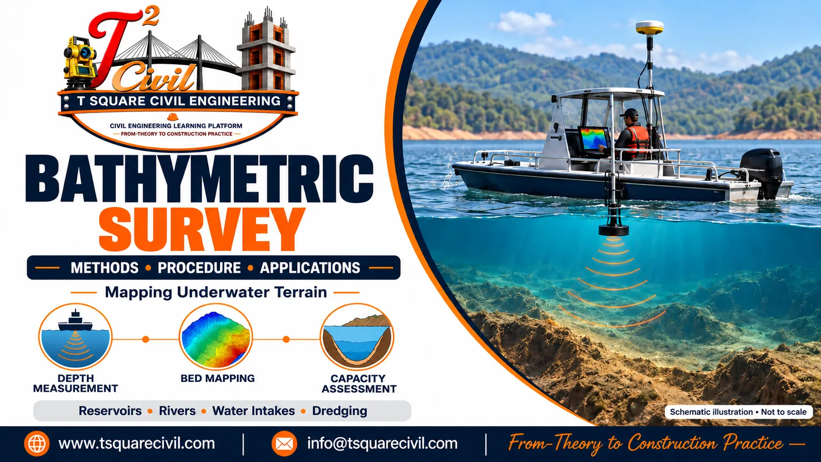
by A bathymetric survey measures water depths and maps the shape and elevation of the bed beneath a river, lake, reservoir, pond or coastal water body. It helps engineers understand underwater conditions that cannot be assessed by looking at the water surface alone.
In civil engineering, bathymetric surveys support reservoir capacity calculations, water intake planning, dredging, underwater pipeline alignment and investigation of riverbed changes.
A reliable survey involves more than collecting depth readings. Each measurement must have a known position, a suitable elevation reference and appropriate quality checks. The results should show where measurements were collected, how they were processed and what limitations remain.
This guide explains bathymetric survey methods, equipment, procedures, calculations and practical applications, with examples relevant to civil engineering projects.
Page Contents
What Is a Bathymetric Survey?
A bathymetric survey is the measurement and mapping of underwater terrain.
It records depth observations at known locations and uses them to develop a representation of the submerged bed. An individual depth observation is commonly called a sounding.
A typical survey dataset includes:
- Horizontal coordinates of the observations.
- Measured depths or acoustic ranges.
- Time of measurement.
- Information needed to establish the vertical reference.
- Calculated bed elevations.
- Survey quality and processing records.
The final results may include underwater contours, longitudinal profiles, cross-sections and a digital bed model.
For example, a reservoir that appears uniform from the bank may contain a deep channel, shallow sediment deposits and steep underwater slopes. A bathymetric survey helps identify these features within the limits of its coverage and resolution.
Bathymetric Survey vs Hydrographic Survey vs Topographic Survey
These surveys are related, but their scope differs.
| Survey type | Main purpose | Typical outputs |
|---|---|---|
| Bathymetric survey | Measure underwater depths and map bed geometry | Soundings, bed elevations, underwater contours and sections |
| Hydrographic survey | Describe water bodies and features relevant to navigation, engineering or other uses | Bathymetry, shoreline information and, where required, water levels, currents and hazards |
| Topographic survey | Map land surfaces and visible features | Ground elevations, contours, roads, buildings and other surface features |
Bathymetry forms an important part of hydrographic surveying.
Many civil engineering projects need both bathymetric and topographic information. For a water intake project, the underwater survey may need to connect with the bank, pipeline route, access road and pump-house site.
These datasets should use compatible coordinate systems and elevation references.
Why Is Bathymetric Survey Important?
Bathymetric information helps engineers answer questions such as:
- Where is the deeper channel?
- How much depth will remain at a proposed intake during low-water conditions?
- What is the underwater bed profile along a pipeline route?
- What storage volume corresponds to a particular reservoir level?
- Where has sediment accumulated?
- How has the bed changed since an earlier survey?
- What quantity of material may need to be dredged?
The survey specification should follow the engineering purpose. A general reservoir study and a detailed investigation around an intake structure may require different coverage, accuracy and deliverables.
Applications of Bathymetric Survey in Civil Engineering
Reservoir Capacity Assessment
A surveyed bed model can be used to calculate water-spread area and storage volume at selected elevations.
The results are often presented as an elevation–area–capacity table, which relates:
- Water-surface elevation.
- Water-spread area at that elevation.
- Cumulative storage volume below that elevation.
Where capacity calculations extend above the survey water level, reliable topographic information for the exposed reservoir margins is also required.
Water Intake Planning
Bathymetry helps identify potential intake locations and assess the bed geometry around them.
It is especially useful where seasonal water-level changes cause the shoreline to move considerably.
Dredging and Desilting
Surveys before and after dredging help assess changes in bed elevation and calculate quantities within agreed boundaries.
Underwater Pipeline Alignment
A survey can reveal slopes, depressions and irregularities along a proposed pipeline corridor. These findings help guide route selection and further investigation.
Riverbed and Scour Monitoring
Repeated surveys can identify bed-level changes near bridges, barrages, river training works and other structures.
The interpretation of scour risk also requires hydraulic, structural and geotechnical information.
Lake and Pond Improvement Works
Bathymetric information can support storage assessment, desilting planning and the development of bed profiles for restoration projects.
Water Depth and Bed Elevation Are Different
Understanding this difference is essential when interpreting a bathymetric survey.
Water depth is the vertical distance between the water surface and the bed at a particular location and time.
Bed elevation, often called bed reduced level or bed RL, is the elevation of the bed relative to a stated vertical datum.
A vertical datum is the reference from which elevations are measured. A benchmark is a physical reference point with a known elevation in that system.
Water depth changes when the water level rises or falls. Bed elevation changes when the bed itself changes through erosion, deposition, excavation or other processes.
Formula for Bed RL
When the depth has been corrected to represent the vertical distance below the water surface:
Bed RL = Water-surface RL − Corrected water depth
Both elevations must use the same vertical datum.
Worked Example
Assume:
- Water-surface RL during the survey = 105.20 m
- Corrected water depth = 6.40 m
Therefore:
Bed RL = 105.20 − 6.40 = 98.80 m
If the adopted low-water RL is 101.50 m:
Depth at low water = 101.50 − 98.80 = 2.70 m
Although the measured depth during the survey was 6.40 m, the calculated depth at the adopted low-water level is only 2.70 m.
This calculation assumes that the bed remains unchanged.
For intake planning, assess depths at the relevant operating water levels, not only at the water level observed during the survey.
Main Bathymetric Survey Methods
1. Manual Sounding
Manual sounding uses a graduated pole, sounding rod or weighted line to measure depth.
It can be useful for:
- Small ponds.
- Accessible shallow areas.
- Local verification.
- Locations where a survey vessel cannot operate.
Limitations include fewer observations, difficulty keeping a line vertical in flowing water and uncertainty where the rod or weight penetrates soft sediment.
The survey team should define the bed surface being measured and use a method appropriate to the required accuracy.
2. Single-Beam Echo Sounding
A single-beam echo sounder measures acoustic range beneath a transducer.
The survey vessel follows planned lines while the equipment records soundings and positions. These observations describe the bed along the vessel tracks.
Single-beam equipment can suit many engineering projects when survey spacing, check lines and system performance meet the specified requirements.
However, features between the surveyed tracks may remain undetected.
A smooth surface generated between widely spaced tracks does not mean that the entire bed was directly measured.
3. Multibeam Echo Sounding
A multibeam echo sounder measures multiple acoustic ranges across a swath beneath and beside the vessel.
With suitable positioning, motion compensation, sound-speed information and survey coverage, it can produce detailed underwater mapping.
Multibeam surveys require careful system installation, calibration, data processing and quality control.
They are particularly useful where detailed bed information or extensive coverage is required.
4. Bathymetric LiDAR
Bathymetric LiDAR uses specialised laser equipment to measure suitable shallow-water terrain from an airborne platform.
Its effectiveness depends on water clarity, depth, surface conditions, bottom reflectivity and equipment capability.
Turbidity and vegetation can limit the measurements. Its suitability should therefore be assessed for the actual site.
Survey Platforms: Crewed Boats and Uncrewed Surface Vessels
Bathymetric equipment may be carried on a crewed boat or an uncrewed surface vessel.
An uncrewed vessel can improve access to some shallow or restricted areas, but its suitability depends on:
- Water depth.
- Currents and waves.
- Vegetation and floating debris.
- Communication coverage.
- Endurance and payload.
- Launching and recovery arrangements.
The vessel is the survey platform. The equipment and survey method determine how depth is measured.
Using an uncrewed vessel does not automatically make a survey more accurate.
Single-Beam vs Multibeam Survey
| Aspect | Single-beam survey | Multibeam survey |
|---|---|---|
| Measurement pattern | Soundings along vessel tracks | Multiple soundings across a swath |
| Coverage | Depends on track spacing and acoustic footprint | Depends on swath width, overlap and accepted data |
| Bed detail | Suitable for many profile and general mapping tasks | Often suitable for detailed bed mapping |
| System complexity | Generally lower | Generally higher |
| Feature detection | Features between tracks may be missed | Better potential with appropriate coverage and resolution |
| Selection basis | Required performance and site conditions | Required performance and site conditions |
Neither method should be selected only because it is cheaper or more advanced. The chosen system must meet the project’s requirements for coverage, uncertainty and feature detection.
Instruments Used in Bathymetric Survey
A survey may use the following equipment:
| Equipment | Main function |
|---|---|
| Echo sounder and transducer | Measure acoustic ranges to the bed |
| Survey-grade GNSS equipment | Determine survey positions |
| RTK or differential positioning system | Improve positioning where suitable |
| Sound-speed instrument | Provide information for acoustic corrections |
| Motion and heading sensors | Measure vessel movement and orientation where required |
| Water-level gauge or surveyed observations | Support vertical referencing |
| Level or total station | Establish control and survey shoreline features |
| Data acquisition system | Record and integrate measurements |
| Survey vessel | Carry the equipment |
GNSS means Global Navigation Satellite System. GPS is one of the satellite systems included within GNSS.
How Does an Echo Sounder Measure Depth?
An echo sounder sends an acoustic pulse towards the bed and measures the time taken for the reflected signal to return.
For a simplified vertical measurement using a representative sound speed:
Acoustic range = c × t ÷ 2
Where:
- c = sound speed in water, in m/s.
- t = two-way travel time, in seconds.
The division by two accounts for the outward and return journeys.
Worked Example
Assume:
- Sound speed = 1,480 m/s
- Two-way travel time = 0.008 seconds
Then:
Acoustic range = 1,480 × 0.008 ÷ 2
Acoustic range = 5.92 m
This is the simplified range below the transducer. It is not automatically the final water depth below the water surface.
Processing must account for the instrument reference, transducer immersion and other applicable corrections.
The sound speed of 1,480 m/s is an illustrative value. Actual surveys should use sound-speed information appropriate to the site and equipment.
Bathymetric Survey Procedure Step by Step
Step 1: Define the Survey Purpose and Boundary
Identify the engineering decisions that the survey must support.
For an intake project, coverage may include candidate intake locations, connecting channels, the underwater pipeline corridor and the shoreline connection.
For a storage study, coverage may include the submerged reservoir basin and its connection with topographic data above the water level.
State the boundary, performance requirements and deliverables before fieldwork begins.
Step 2: Review Existing Information
Collect and assess available:
- Previous survey drawings.
- Site plans.
- Water-level records.
- Benchmark information.
- Existing structure details.
- Access restrictions.
- Operating constraints.
- Records of known underwater obstacles.
Check the age, reference system, coverage and reliability of earlier information before using it.
Step 3: Establish Survey Control
Identify or establish suitable horizontal and vertical control.
Document:
- Coordinate reference system.
- Map projection and units.
- Vertical datum.
- Benchmark locations and elevations.
- Transformations used between reference systems.
A GNSS ellipsoidal height should not automatically be treated as a project RL. The required transformation or surveyed connection must be established.
Step 4: Plan Survey Lines and Coverage
Prepare the main survey lines and independent check lines.
Provide additional detail where required around:
- Intake locations.
- Abrupt bed changes.
- Pipeline crossings.
- Dredging boundaries.
- Suspected obstructions.
- Structures or other critical areas.
There is no universal line spacing suitable for every project. The spacing and coverage should reflect the required uncertainty, terrain and smallest important feature.
Step 5: Install and Check the Equipment
Secure the transducer and other sensors and measure their relative positions.
Check:
- Equipment settings.
- Sensor offsets.
- Time synchronisation.
- Transducer immersion.
- Positioning quality.
- Data recording.
- Applicable calibration results.
For suitable single-beam systems, a bar check can help verify depth performance. Multibeam systems require the relevant alignment and calibration procedures.
Step 6: Establish Water-Level and Sound-Speed Information
Record water-level information at intervals appropriate to how quickly conditions change.
In rivers and long survey reaches, water-surface elevation may also vary along the channel. Use appropriately located observations or another validated vertical-referencing method so that each sounding receives the correct elevation reference.
Obtain sound-speed measurements appropriate to the water column, equipment and required accuracy.
Step 7: Collect Soundings
Follow the planned survey lines at a suitable speed.
Monitor:
- Depth traces.
- Positioning status.
- Coverage.
- Sensor performance.
- Data quality.
- Changes in site conditions.
Mark questionable areas for investigation and collect additional data where needed.
Maintain a field log of interruptions, equipment adjustments and relevant observations.
Step 8: Collect Independent Check Lines
Use check lines to compare results with the main survey.
Investigate discrepancies rather than simply averaging conflicting measurements.
Possible causes include incorrect offsets, positioning problems, water-level changes, sound-speed errors or inconsistent bottom detection.
Step 9: Process and Validate the Data
Apply the relevant corrections and review suspect observations.
Maintain a record of significant editing and processing decisions.
Create the accepted bed model, contours and sections while identifying gaps, excluded data and areas based mainly on interpolation.
Step 10: Prepare the Report and Drawings
The final package should explain:
- What was surveyed.
- Where measurements were collected.
- Which references were used.
- How corrections were applied.
- How quality was assessed.
- What limitations remain.
Important Corrections and Quality Checks
Transducer Immersion
If the sounder reports range below the transducer, the transducer’s immersion below the water surface must be accounted for when calculating water-surface depth.
Do not apply this offset again if the acquisition or processing system has already included it.
Sound Speed
An incorrect sound-speed value affects the calculated acoustic range.
Changes in sound speed through the water column also influence acoustic paths, which is particularly important for multibeam measurements.
Vessel Motion
Heave, roll and pitch can affect measurements. The required treatment depends on the equipment, operating conditions and accuracy requirements.
Position and Timing
Each sounding must be assigned to the correct position and time.
Incorrect sensor offsets or timing can distort the mapped bed, especially where slopes are steep.
Bottom Detection
Vegetation, debris, suspended material and soft sediment may complicate identification of the required bed surface.
The processing method should be appropriate to the survey purpose and documented in the report.
Bathymetric Survey Accuracy and Standards
Accuracy requirements should apply to the complete survey system.
A specification should address:
- Horizontal uncertainty.
- Vertical uncertainty.
- Confidence level.
- Survey coverage.
- Feature detection where relevant.
- Control verification.
- Quality checks.
- Reporting requirements.
The International Hydrographic Organization’s S-44 Standards for Hydrographic Surveys provide a recognised framework for hydrographic survey requirements. The reference edition used for this article is Edition 6.2.0, October 2024.
IHO S-44 is an international hydrographic survey standard, not an Indian Standard issued by BIS. For projects in India, identify the applicable employer specifications, authority requirements and adopted survey standard in the project documents.
Simply stating “survey as per IHO standards” is insufficient unless the applicable requirements and acceptance criteria are identified.
Accuracy Is Different from Resolution
Instrument resolution, survey uncertainty, model grid size and contour interval describe different things.
A model with small grid cells does not automatically have equally small measurement uncertainty. Similarly, a fine contour interval does not prove that the underlying observations support that level of detail.
Bathymetric Survey for Water Intake and WTP Projects
For a water treatment plant, bathymetry helps assess potential raw-water intake locations and the route connecting them to shore.
The survey should consider the relevant area around:
- Candidate intake points.
- Connecting channels.
- Underwater pipeline corridors.
- Shoreline transitions.
- Potential mooring or anchor locations.
- Shallow zones and abrupt bed changes.
Intake Depth Calculation at Low Water
Assume:
- Survey water-surface RL = 110.00 m
- Corrected depth = 8.00 m
- Adopted minimum operating water-level RL = 104.00 m
First calculate bed RL:
Bed RL = 110.00 − 8.00 = 102.00 m
Then calculate depth at minimum operating level:
Available depth = 104.00 − 102.00 = 2.00 m
The location has 8 m of water during the survey but only 2 m at the adopted minimum operating level, assuming unchanged bed conditions.
Whether 2 m is adequate depends on the intake arrangement, required submergence, clearance above the bed, hydraulic conditions and operating requirements.
Additional Investigations Required
Bathymetry provides geometry. Intake design may also require:
- Seasonal water-level and availability assessment.
- Raw-water quality testing.
- Current and wave information.
- Sediment investigation.
- Geotechnical investigation.
- Hydraulic calculations.
- Pump selection.
- Mooring and stability calculations for floating systems.
The bed profile alone cannot establish anchor resistance or foundation bearing capacity.
Can Bathymetric Survey Confirm Year-Round Water Availability?
A single bathymetric survey cannot independently confirm year-round water availability.
It records underwater geometry associated with a particular survey period.
An all-season assessment also needs appropriate water-level records, reservoir operating information, dry-season conditions and an understanding of hydraulic connectivity.
A deep pocket may retain water while becoming isolated from the main reservoir.
For intake planning, assess the connecting channel as well as the proposed intake point.
Reservoir Capacity Calculation Using Bathymetry
A bed model can be used to estimate storage below selected water-surface elevations.
One approximate method between adjacent elevation contours is the trapezoidal formula:
V = Δh × (A₁ + A₂) ÷ 2
Where:
- V = volume between the two elevations, in m³.
- Δh = elevation difference, in m.
- A₁ and A₂ = enclosed water-spread areas at those elevations, in m².
Worked Example
Assume:
- Water-spread area at RL 100 m = 20,000 m²
- Water-spread area at RL 101 m = 24,000 m²
- Elevation interval = 1 m
Then:
V = 1 × (20,000 + 24,000) ÷ 2
V = 22,000 m³
This is the approximate volume between RL 100 m and RL 101 m.
Cumulative storage requires adding the volumes of the relevant elevation intervals, including any volume below the lowest interval used.
The trapezoidal method approximates how area changes between elevations. Its suitability depends on the terrain and interval size.
To calculate storage above the survey water level, combine the underwater bed model with reliable topographic data for exposed banks and reservoir margins. Both datasets must use compatible horizontal and vertical references.
Sedimentation Assessment Using Repeated Surveys
Repeated surveys can reveal changes in bed elevation.
For an illustrative example:
- Comparison area = 10,000 m²
- Area-weighted mean bed rise = 0.25 m
Then:
Estimated volume increase = 10,000 × 0.25
Estimated volume increase = 2,500 m³
This represents an estimated in-place volume increase, assuming that the bed rise is attributable to sediment deposition.
Where erosion and deposition both occur, calculate them separately if gross erosion and deposition quantities are needed. Their difference represents net bed-volume change.
Before comparing surveys, check:
- Vertical datum.
- Coordinate system.
- Common comparison boundary.
- Survey coverage.
- Bottom-detection approach.
- Measurement uncertainty.
- Model processing.
Differences between incompatible surveys can appear as bed changes even when part of the difference comes from measurement or processing.
Bathymetric Survey for Dredging Quantities
Dredging quantity assessment usually involves comparing accepted bed surfaces within agreed boundaries.
Depending on the purpose, the calculation may compare:
- The existing bed with a design dredging surface.
- Pre-dredging and post-dredging surfaces.
- The completed bed with the specified acceptance surface.
The contract should define:
- Survey method and quality requirements.
- Design dredging limits.
- Quantity calculation boundaries.
- Treatment of side slopes.
- Permitted tolerances.
- Treatment of over-dredging.
- Joint verification and acceptance procedures.
An in-place dredged volume should not automatically be treated as the same volume measured in a stockpile or transport vehicle.
Bathymetric Survey Deliverables
| Deliverable | Purpose |
|---|---|
| Survey report | Explain methods, references, processing and limitations |
| Track and coverage plan | Show where data were collected |
| Sounding plan | Present accepted depths or bed elevations |
| Bed contour plan | Show underwater terrain |
| Longitudinal profiles | Support route and channel assessment |
| Cross-sections | Show local bed geometry |
| Digital bed model | Support design and volume calculations |
| XYZ dataset | Provide coordinates and bed elevations |
| Water-level records | Support vertical referencing |
| Calibration and quality records | Document survey checks |
| Raw and processed data | Support review and future comparison |
| Elevation–area–capacity table | Present storage information where required |
The specification should identify required file formats, units and reference systems.
For an XYZ dataset, clearly state what each column represents. For example, X and Y may represent easting and northing, while Z represents bed elevation in metres relative to the specified datum.
Bathymetric Survey Tender Scope Checklist
A clear tender should define the following:
- Survey purpose: the engineering decisions supported.
- Survey boundary: the area and corridors to be covered.
- Reference systems: coordinates, vertical datum and benchmark connections.
- Performance requirements: uncertainty, coverage and feature detection.
- Survey planning: main lines, check lines and critical areas.
- Field requirements: calibration, sound-speed information and vertical referencing.
- Additional investigations: shoreline survey, sediment sampling or other work where required.
- Deliverables: drawings, models, datasets and report formats.
- Acceptance procedure: quality review, discrepancy investigation and re-survey requirements.
- Commercial basis: measurement units, inclusions, mobilisation and payment conditions.
Terms such as “complete bathymetric survey” should be supported by measurable requirements.
What Affects Bathymetric Survey Cost?
The cost depends on the work required to meet the specified performance.
Important factors include:
- Survey area and water depth.
- Required coverage and detail.
- Equipment and platform.
- Mobilisation distance and access.
- Currents, waves and vegetation.
- Control establishment.
- Processing effort.
- Additional investigations.
- Required deliverables.
Quotations are meaningful only when the scope and acceptance requirements are comparable.
Common Mistakes to Avoid
Using Survey-Date Depth for Low-Water Design
Calculate the available depth at the relevant operating water level using the surveyed bed elevation.
Omitting the Vertical Datum
A bed RL is incomplete without its elevation reference.
Assuming Complete Coverage from Sparse Soundings
Interpolation estimates the surface between observations. It does not prove that no feature exists between survey tracks.
Confusing Grid Size with Accuracy
A fine grid can contain interpolated values and uncertain observations.
Ignoring Changes in Water Level Along a River
Water-surface elevation may vary with both time and location.
Comparing Incompatible Surveys
Differences in references, coverage or processing can distort sedimentation estimates.
Treating Bathymetry as a Geotechnical Investigation
Bed geometry does not establish soil strength, bearing capacity or anchor resistance.
Retaining Only Final Drawings
Keep suitable raw data, processed data, control records and quality documentation for future review.
Frequently Asked Questions
What is the main purpose of a bathymetric survey?
It measures underwater depths and maps bed geometry for applications such as intake planning, storage assessment, dredging and underwater route investigation.
What is a sounding?
A sounding is an individual depth measurement. Surveyed soundings are associated with positions and a defined reference.
What is a bathymetric contour?
It is a line joining points of equal underwater elevation or equal depth. The drawing must identify which convention and reference are used.
Is GPS alone sufficient for a bathymetric survey?
No. Positioning equipment identifies location, while suitable depth measurements and vertical referencing are also required.
What is the difference between water depth and bed RL?
Water depth is measured below the water surface at a particular time. Bed RL is the elevation of the bed relative to a stated datum.
Can bathymetric survey measure sediment thickness?
An ordinary bed survey does not automatically determine the full thickness of sediment. Sub-bottom investigation, cores or other suitable methods may be required.
Repeated compatible surveys can estimate changes in bed level and storage over time.
Can a drone conduct a bathymetric survey?
Specialised airborne systems can measure bathymetry under suitable conditions. Ordinary aerial photographs do not reliably establish submerged bed elevations in every water body.
Is multibeam compulsory for every project?
No. The selected method should meet the project’s requirements. An appropriately specified single-beam survey can be suitable for many engineering purposes.
How often should a bathymetric survey be repeated?
The interval depends on the purpose, expected bed changes and operational needs. Significant floods, dredging or intake problems may justify a fresh survey.
Can bathymetry confirm that an intake will operate throughout the year?
It helps calculate depths at relevant water levels, but year-round operation also depends on water availability, connectivity, hydraulics and the intake design.