 by
Page Contents
Introduction
A foundation is the lowest structural part of a building or other structure. It transfers structural loads safely to the supporting soil or rock.
A properly designed foundation should:
- Transfer structural loads safely to the ground
- Keep soil pressure within acceptable limits
- Control total and differential settlement
- Provide stability against sliding and overturning
- Resist uplift and lateral loads
- Protect the structure from ground and water-related problems
Foundation selection should not be based only on the number of floors. It depends on structural loads, soil conditions, groundwater, settlement, site restrictions, adjacent structures, construction methods and project requirements.
For more civil engineering topics, construction guides and practical learning resources, visit the Civil Engineering Articles section of T Square Civil Engineering.
What Is a Foundation?
A foundation is the substructure provided below a building or other structure to transfer loads safely to the ground.
The foundation distributes the structural load over an adequate soil area or transfers it to deeper soil or rock layers.
The main purposes of a foundation are:
- To support the structure safely
- To reduce excessive soil pressure
- To control settlement
- To prevent uneven movement
- To provide stability against overturning and sliding
- To protect the structure from soil and groundwater effects
Difference Between Foundation and Footing
The terms foundation and footing are related but have different meanings.
A foundation is the complete substructure that transfers structural loads to the ground.
A footing is one type of foundation element used to spread the load from a column or wall over a larger area of soil.
Examples include:
- Isolated footing for one column
- Combined footing for two or more columns
- Strip footing below a load-bearing wall
- Raft foundation below several columns and walls
- Pile foundation using piles and pile caps
Load Transfer Through a Foundation
A typical load path is:
Floor and roof systems → Beams, columns or walls → Foundation system → Supporting soil or rock
A foundation may be required to resist:
- Dead load
- Live load
- Wind load
- Earthquake load
- Lateral load
- Uplift
- Bending moment
- Shear force
- Construction-stage loads
The actual design loads must be taken from approved structural drawings and design calculations.
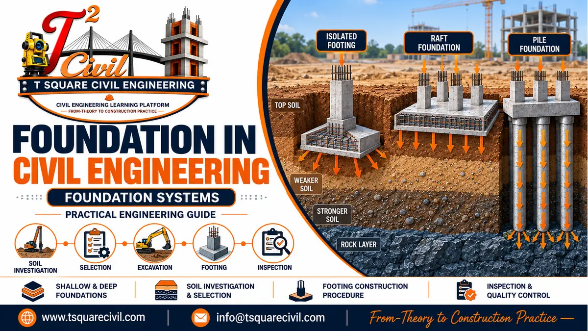
Classification of Foundations
Foundations are generally divided into two main groups:
- Shallow foundations
- Deep foundations
Shallow Foundations
Shallow foundations transfer structural loads to soil close to the ground surface.
They are generally used when the near-surface soil has adequate strength and expected settlement is within acceptable limits.
Common types include:
- Isolated footing
- Combined footing
- Strip footing
- Strap footing
- Raft or mat foundation
- Stepped foundation
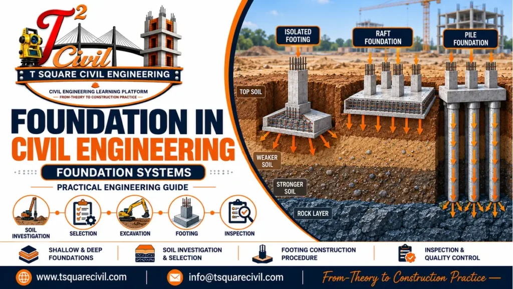
Deep Foundations
Deep foundations transfer structural loads to deeper soil or rock layers.
The load may be transferred through:
- End bearing at the base
- Skin friction along the shaft
- A combination of end bearing and skin friction
Deep foundations may be required when the near-surface soil is weak, compressible, expansive or unsuitable for supporting the structure.
Common types include:
- Pile foundation
- Under-reamed pile
- Pier foundation
- Caisson or drilled shaft foundation
Types of Foundations
| Foundation type | Basic function | Common application |
|---|---|---|
| Isolated footing | Supports one column | Adequate soil and sufficient column spacing |
| Combined footing | Supports two or more columns | Closely spaced columns or boundary restrictions |
| Strip footing | Supports a continuous wall load | Load-bearing walls |
| Strap footing | Connects two separate footings | Boundary columns and eccentric loading |
| Raft foundation | Supports several columns or walls over a large area | Low bearing capacity or closely spaced columns |
| Pile foundation | Transfers load to deeper soil or rock | Weak surface soil or heavy loads |
| Under-reamed pile | Provides deep support with enlarged bulbs | Expansive soil conditions |
Isolated Footing
An isolated footing supports a single column.
It may be:
- Square
- Rectangular
- Circular
- Stepped
- Sloped
Isolated footings are commonly used when:
- Columns are sufficiently separated
- Near-surface soil has adequate bearing capacity
- Settlement is acceptable
- Footing areas do not overlap
- There are no major boundary restrictions
The footing size, depth, thickness and reinforcement must be determined by structural and geotechnical design.
Combined Footing
A combined footing supports two or more columns on one foundation base.
It may be required when:
- Two columns are close together
- Individual footings would overlap
- A column is close to a property boundary
- An eccentric load arrangement must be controlled
Combined footings may be rectangular or trapezoidal depending on the column positions and load distribution.
The design should consider:
- Column loads
- Column spacing
- Resultant load location
- Soil pressure distribution
- Bending and shear
- Settlement compatibility
Strip Footing
A strip footing is a continuous footing provided below a load-bearing wall or a closely spaced line of columns.
It spreads the wall load over a wider soil area and reduces contact pressure.
Typical construction stages include:
- Setting out the wall line
- Excavating the foundation trench
- Inspecting the excavation bottom
- Placing PCC or approved levelling material
- Providing reinforcement where specified
- Placing concrete
- Curing and backfilling
Strap Footing
A strap footing consists of two separate footings connected by a reinforced concrete strap beam.
It is commonly used when:
- An exterior column is close to a property boundary
- The exterior footing cannot be centred below the column
- A connecting beam is required to control eccentricity
The strap beam transfers forces between the footings. It should not automatically be assumed to act as a soil-bearing element unless this is specifically shown in the approved design.
Raft or Mat Foundation
A raft foundation is a large reinforced concrete foundation supporting several columns, walls or a major portion of a building.
It may be considered when:
- Soil bearing capacity is relatively low
- Columns are closely spaced
- Individual footings would occupy a large part of the building area
- Settlement control is important
- A raft forms part of a basement foundation system
A basement does not automatically require a raft foundation.
Common forms of raft foundation include:
- Flat raft
- Beam-and-slab raft
- Cellular raft
- Thickened raft
- Ribbed raft
A raft foundation is not automatically the best solution for every weak-soil condition. Its suitability depends on soil investigation, structural loads, settlement analysis, groundwater and construction requirements.
Pile Foundation
A pile foundation uses long structural elements installed in the ground to transfer loads to deeper soil or rock.
Piles may be:
- Bored cast-in-situ piles
- Driven cast-in-situ piles
- Precast concrete piles
- Steel piles
- Timber piles
- Under-reamed piles
Pile foundations may be used for:
- High-rise buildings
- Bridges
- Industrial structures
- Marine structures
- Weak or compressible surface soils
- Structures subject to uplift or lateral loads
- Sites where shallow foundations may cause excessive settlement
Piles do not always need to reach rock. Depending on the soil profile and design, they may transfer load through end bearing, skin friction or both.
Site Investigation Before Foundation Construction
Foundation selection should not be finalized without sufficient information about the ground.
Desk Study
A desk study may review:
- Previous site use
- Existing drawings
- Geological information
- Nearby construction experience
- Flooding or erosion history
- Existing utilities
- Adjacent foundation conditions
Site Reconnaissance
The site should be inspected for:
- Visible cracks or settlement
- Filled ground
- Soft or loose areas
- Waterlogging
- Existing structures
- Sloping ground
- Nearby excavation
- Drainage problems
Boreholes and Trial Pits
These investigations help identify:
- Soil layers
- Depth of hard strata
- Fill material
- Organic soil
- Weathered rock
- Groundwater level
Field Tests
Depending on the project, field testing may include:
- Standard Penetration Test
- Plate load test
- In-situ density testing
- Vane shear testing
- Permeability testing
- Other approved geotechnical tests
For related testing procedures and material-testing resources, refer to the Civil Engineering Lab Test hub.
Laboratory Tests
Laboratory testing may determine:
- Grain-size distribution
- Atterberg limits
- Moisture content
- Shear strength
- Consolidation characteristics
- Compaction characteristics
- Density and specific gravity
Geotechnical Report
A foundation investigation report should provide project-specific information such as:
- Soil profile
- Groundwater conditions
- Allowable bearing pressure
- Expected settlement
- Recommended foundation type
- Excavation conditions
- Backfilling requirements
- Ground-improvement recommendations
One isolated soil test should not be used as the complete basis for foundation design.
Factors Affecting Foundation Selection
Structural Load
The foundation must be designed for the actual:
- Axial load
- Bending moment
- Shear force
- Lateral load
- Uplift
- Construction load
Soil Bearing Capacity
The soil must safely support the foundation pressure without shear failure.
However, a foundation may still be unsuitable if excessive settlement develops, even when shear failure does not occur.
Settlement
Settlement may include:
- Immediate settlement
- Consolidation settlement
- Differential settlement
Unequal settlement may cause:
- Wall cracks
- Sloping floors
- Door and window problems
- Separation between structural and non-structural elements
- Structural distress
Groundwater
Groundwater may affect:
- Excavation stability
- Soil strength
- Concrete placement
- Dewatering requirements
- Waterproofing
- Durability and corrosion
Expansive Soil
Expansive soil may swell when wet and shrink when dry. This repeated movement can damage shallow foundations.
Possible solutions may include:
- Increased foundation depth
- Under-reamed piles
- Soil replacement
- Ground improvement
- Moisture-control measures
The final solution must be based on geotechnical design.
Adjacent Structures
Foundation construction near existing buildings may cause:
- Loss of soil support
- Ground movement
- Damage to neighbouring foundations
- Water migration
- Vibration-related problems
Temporary support, staged excavation or specialist advice may be required.
General Foundation Construction Procedure
Step 1: Review Approved Documents
Before starting work, verify:
- Structural drawings
- Foundation layout
- Geotechnical report
- Levels and benchmarks
- Concrete grade
- Reinforcement details
- Excavation requirements
- Inspection and testing requirements
Step 2: Setting Out
Mark the foundation using approved reference points.
Check:
- Grid lines
- Column locations
- Centre lines
- Diagonals
- Offsets
- Property boundaries
- Foundation dimensions
Setting out should be independently checked before excavation.
Step 3: Excavation
Excavate to the specified length, width and depth.
During excavation, check:
- Soil type
- Loose material
- Soft pockets
- Water
- Unauthorised over-excavation
- Excavation-side stability
- Nearby structures and utilities
Unsafe excavation sides must not be left unsupported.
Step 4: Bottom Inspection
Before placing PCC or concrete, inspect the excavation bottom.
The bottom should be:
- At the correct level
- Free from loose soil
- Free from organic material
- Free from standing water
- Properly compacted where required
- Accepted by the responsible engineer or inspector
If unsuitable soil is found, do not simply cover it with concrete. Obtain a project-specific instruction.
Step 5: Dewatering
If water enters the excavation, use an approved dewatering arrangement.
Dewatering should not cause:
- Soil erosion
- Piping
- Loss of fines
- Settlement of nearby structures
- Instability of excavation sides
Step 6: PCC or Levelling Course
PCC may be provided to:
- Create a clean working surface
- Provide a level base
- Separate structural concrete from soil
- Provide a clean, level base that helps position reinforcement and cover blocks correctly
- Reduce contamination of structural concrete
The PCC grade and thickness must follow the approved drawing, BOQ or project specification. No single PCC grade or thickness is suitable for every project.
Step 7: Reinforcement Placement
Check:
- Bar diameter
- Bar spacing
- Bar direction
- Development length
- Anchorage
- Laps, where permitted
- Concrete cover
- Column starter location
- Reinforcement cleanliness
- Stability of reinforcement during concreting
For reinforcement terminology, steel grades and testing information, refer to the Complete Reinforcement Steel Guide.
Where required, the Lap Length Calculator and BBS Calculator may assist with preliminary reinforcement checks.
Reinforcement should not be placed directly on soil. Approved cover blocks or supports should be used.
Step 8: Formwork and Starter Bars
Inspect:
- Footing dimensions
- Formwork alignment
- Formwork stability
- Concrete cover
- Column starter position
- Level and verticality
- Cleanliness
- Tightness of joints
Step 9: Concrete Placement
Before concrete placement, verify:
- Concrete grade
- Approved mix
- Delivery details
- Workability requirement
- Placing method
- Availability of vibrators
- Cube-sampling requirements
- Weather and site conditions
Concrete should be placed and compacted properly to avoid honeycombing, segregation and cold joints.
Before and during concreting, the Concrete Cube Casting Procedure and Slump Cone Test resources may be used for general educational guidance.
Step 10: Curing
Begin curing as soon as the concrete surface can be protected without damage.
The curing method and duration should follow the approved project procedure and concrete requirements.
Step 11: Backfilling
Backfill only after the foundation work is inspected and approved.
Backfill should be:
- Suitable material
- Placed in controlled layers
- Properly compacted
- Free from harmful debris
- Placed using an approved method that protects waterproofing from damage
Protection boards or other approved protective measures should be used where specified.
Foundation Inspection Checklist
Before approving foundation concrete, check:
- Approved drawings are available
- Foundation location is correct
- Excavation dimensions are correct
- Foundation level is correct
- Soil condition is acceptable
- Water has been removed or controlled
- PCC level is correct
- Reinforcement diameter and spacing are correct
- Concrete cover is maintained
- Column starters are correctly positioned
- Formwork is stable and clean
- Concrete grade is verified
- Workability checks are completed where required
- Cube samples are taken as specified
- Concrete is properly compacted
- Curing is started
- Inspection records are completed
No universal cover, bar spacing, concrete grade or footing depth should be adopted without checking the approved design.
Common Foundation Problems
Differential Settlement
Different portions of the structure settle by different amounts.
Possible causes include:
- Variable soil conditions
- Unequal foundation loads
- Poor compaction
- Water leakage
- Inadequate investigation
- Construction near existing foundations
Bearing Failure
Bearing failure may occur when soil pressure exceeds the soil’s capacity or when soil conditions are incorrectly assessed.
Expansive Soil Movement
Swelling and shrinkage of expansive soil may cause repeated foundation movement.
Water Ingress
Water may enter through:
- Poor waterproofing
- Cracks
- Construction joints
- Defective drainage
- High groundwater
- Improper backfill
Honeycombing
Honeycombing may result from:
- Poor compaction
- Congested reinforcement
- Leakage from formwork
- Improper placing
- Segregation
Excavation-Related Movement
Uncontrolled excavation or dewatering near existing structures may reduce ground support and cause settlement or cracking.
Common Foundation Mistakes
- Selecting a foundation without soil investigation
- Using one assumed bearing-capacity value for every site
- Fixing foundation depth by habit
- Placing reinforcement directly on soil
- Ignoring groundwater
- Pouring concrete over loose or unsuitable soil
- Using unapproved PCC grade or thickness
- Backfilling before inspection
- Ignoring adjacent structures
- Treating a quantity calculator as a structural design tool
- Copying reinforcement details from another project
- Assuming a pile must always reach rock
- Using standard footing dimensions without structural design
Foundation Quantity and Reinforcement Resources
For preliminary geometric quantity estimation, use the Concrete Volume Calculator.
For excavation, PCC, RCC and BOQ-related calculations, refer to the Building Quantity Estimation Guide.
For steel weight calculations, use the Steel Bar Weight Calculator.
For other construction-related tools, visit the Civil Engineering Calculators hub.
These resources provide quantity or material information only. They do not replace foundation design.
Relevant Indian Standards
The following standards may be relevant depending on the foundation type and project:
- IS 1904:2021 — General requirements for design and construction of foundations in soils
- IS 1892:2021 — Subsurface investigation for foundations
- IS 2131:2025 — Standard Penetration Test of Soil
- IS 6403:1981 — Determination of bearing capacity of shallow foundations
- IS 2911 series — Design and construction of pile foundations
- IS 2911 Part 3:2021 — Under-reamed piles
- IS 2911 Part 4:2013 — Load test on piles
- IS 456:2000 — Plain and reinforced concrete — Code of practice
Always verify the latest applicable edition, amendments, project specifications and authority requirements before using any standard for design or construction.
Frequently Asked Questions
What is a foundation in civil engineering?
A foundation is the substructure that transfers building loads safely to the supporting soil or rock.
What is the difference between a footing and a foundation?
A footing is one type of foundation element. Foundation is the broader term for the complete load-transfer system below the structure.
Which foundation is best for a building?
There is no single best foundation for every building. The selection depends on structural loads, soil, groundwater, settlement and site conditions.
Can foundation depth be fixed for every building?
No. Foundation depth must be determined from soil conditions, structural requirements, groundwater, adjacent structures and approved design documents.
Is a soil test necessary before foundation construction?
A suitable site investigation is essential for reliable foundation selection and design, especially where soil conditions are variable or the structure is heavily loaded.
Do pile foundations always reach rock?
No. Piles may transfer load through end bearing, skin friction or a combination of both.
Is a raft foundation always better than isolated footings?
No. A raft may be suitable in some soil and layout conditions, but the decision requires geotechnical and structural evaluation.
Can this article be used to design a footing?
No. This article provides educational information only. Footing size, depth, reinforcement and concrete details must be designed or verified for the specific project.
Conclusion
Foundation engineering is the connection between the structure and the ground.
A safe foundation requires:
- Proper site investigation
- Correct foundation selection
- Suitable structural and geotechnical design
- Careful construction
- Proper inspection and quality control
The correct foundation cannot be selected using a standard depth or fixed size. It must be based on actual structural loads, soil behaviour, groundwater, settlement requirements and project conditions.
About T Square Civil Engineering
T Square Civil Engineering is an educational platform that explains civil engineering concepts, construction practices, material testing, concrete technology, mix design, quantity estimation and site quality control in simple and practical language.
Our aim is to connect engineering theory with construction practice through original articles, formulas, examples, calculators, checklists and visual explanations.
To learn more about our purpose and approach, visit the About T Square Civil Engineering page.
Disclaimer
The information on this website is provided for educational purposes only.
This article is not a substitute for professional engineering advice, site-specific soil investigation, structural design, approved drawings, project specifications or supervision by qualified professionals.
Foundation type, size, depth, reinforcement, concrete grade, bearing capacity, settlement limits and construction methods must be determined or verified by a qualified civil, structural or geotechnical engineer for the specific project.
Do not use the information, formulas, examples or calculators on this website as the sole basis for construction, estimation, design or decision-making.
T Square Civil Engineering does not accept responsibility for any loss, damage, defect, delay or other consequence resulting from reliance on the information without proper professional verification.
For the complete website disclaimer, visit the T Square Civil Engineering Disclaimer page.