 by
by Page Contents
Introduction
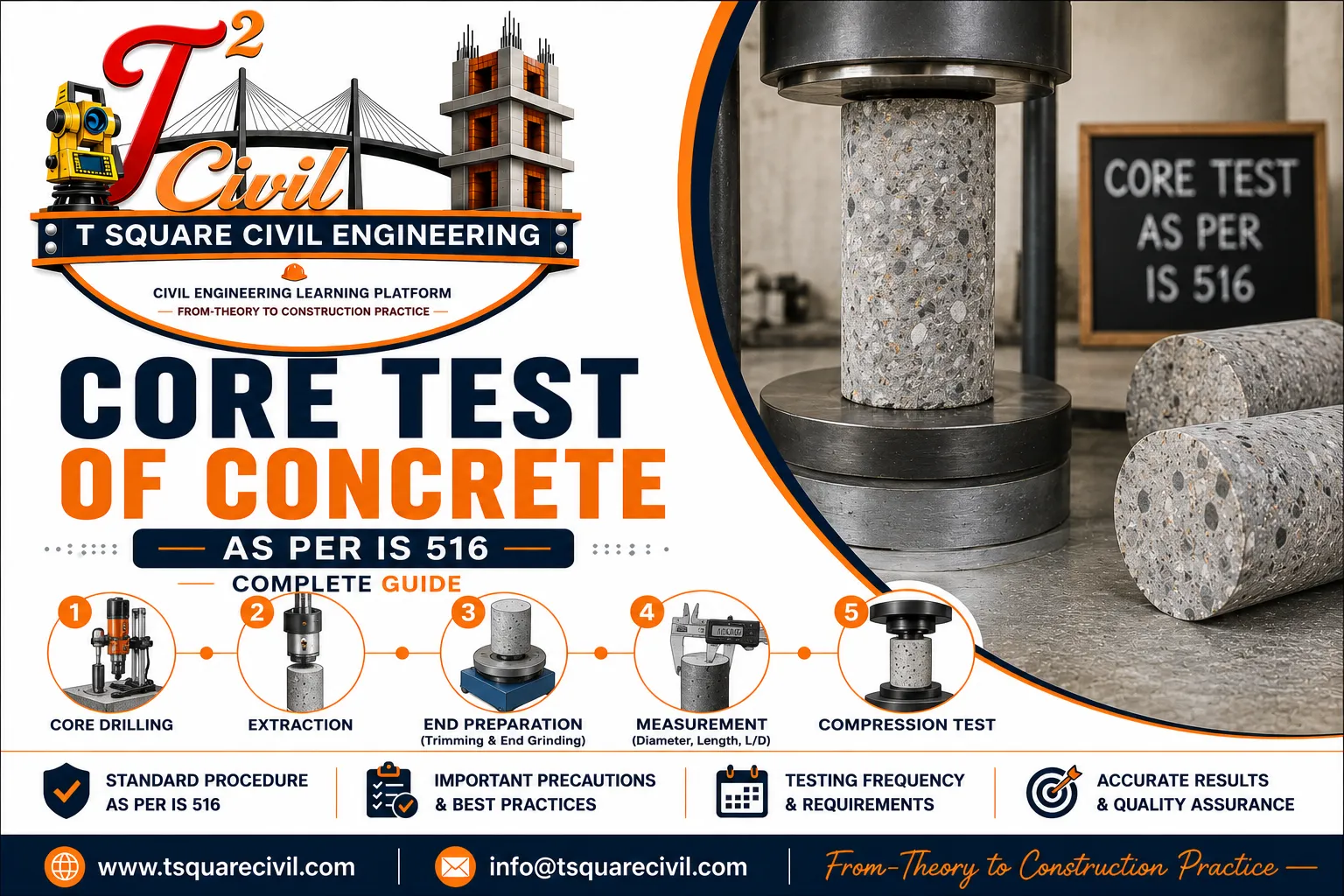
The core test of concrete is a method used to assess the compressive strength of hardened concrete by extracting cylindrical specimens directly from an existing concrete member and testing them under compression.
Unlike cube specimens cast during concreting, a concrete core is taken from the actual hardened structure. It can therefore provide direct information about the concrete present at the selected location.
Core testing is commonly considered when there is doubt about concrete quality, when cube test results are unsatisfactory or questionable, when an existing structure is being assessed, or when direct strength information is required as part of a structural investigation.
In India, sampling, preparation and testing of concrete cores are covered by IS 516 (Part 4):2018, while acceptance of concrete based on core-test results for structures governed by IS 456 is addressed in IS 456:2000, Clause 17.4. BIS documentation lists IS 516 (Part 4):2018 as the standard for sampling, preparing and testing concrete cores.
Quick Answer
A concrete core test involves drilling a cylindrical specimen from hardened concrete, preparing and measuring the specimen, testing it in compression and interpreting the result according to the applicable standard and assessment purpose.
The basic sequence is:
Select Representative Location → Scan Member → Drill Core → Identify & Prepare Core → Measure Dimensions → Compression Test → Apply Applicable Corrections → Interpret Results
The core test is a partially destructive test because concrete is physically removed from the structure.
What Is a Core Test of Concrete?
A concrete core test is performed by extracting a cylindrical sample from hardened concrete using a rotary core-drilling machine fitted with an appropriate cutting bit.
The extracted core is prepared according to the applicable testing procedure and loaded in compression until failure.
The measured compressive strength is initially based on:
where:
- = measured compressive strength of the core
- = maximum compressive load at failure
- = cross-sectional area of the prepared core
However, the measured P/AP/A value should not automatically be treated as the equivalent cube strength used for acceptance. Core dimensions and the applicable corrections and conversion procedures must be considered according to the relevant standard.
This distinction is extremely important.
Why Is a Concrete Core Test Performed?
Core testing may be required when direct information about hardened concrete in a structure is needed.
Typical situations include:
- Doubt regarding the concrete grade or strength
- Unsatisfactory cube-test results
- Suspected poor workmanship
- Investigation of an existing structure
- Assessment before alteration or rehabilitation
- Verification of concrete in a particular structural region
- Investigation following abnormal construction or service conditions
- Correlation with non-destructive test results
- Structural condition assessment
IS 456 specifically permits testing of hardened concrete where there is doubt regarding the grade of concrete, including doubt arising from workmanship or cube-strength results.
Age of Concrete Before Core Extraction
A core intended for strength testing should not be removed until the concrete is sufficiently hard to allow extraction without disturbing the bond between the mortar and coarse aggregate.
As a general guideline in IS 516 (Part 4):2018, for concrete grades up to M25, the concrete should normally be at least 14 days old before cores are extracted.
For higher concrete grades, cores may be taken earlier where appropriate.
The actual timing should also consider the investigation purpose, structural condition and Engineer-in-Charge’s requirements.
Core Test IS Code
Two standards must be clearly distinguished.
IS 516 (Part 4):2018
Hardened Concrete — Methods of Test — Part 4: Sampling, Preparing and Testing of Concrete Cores
This standard deals with the procedures associated with concrete cores, including sampling, preparation and testing. BIS’s current concrete-standard documentation continues to list IS 516 (Part 4):2018 for this purpose.
IS 456:2000
Plain and Reinforced Concrete — Code of Practice
Clause 17.4 — Core Test addresses the use of core results for acceptance of concrete represented by the cores.
A useful way to remember the distinction is:
IS 516 (Part 4) → How the core is sampled, prepared and tested
IS 456 Clause 17.4 → Acceptance of represented concrete
Do not confuse the two roles.
Principle of Concrete Core Testing
The principle is straightforward.
A cylindrical specimen is physically removed from the hardened concrete member.
The specimen is prepared to obtain suitable dimensions and end conditions and is then subjected to axial compression.
The failure load is recorded.
The measured core strength is calculated from the failure load and cross-sectional area, after which the applicable corrections and interpretation procedures are followed.
Conceptually:
Existing Concrete
↓
Extract Representative Core
↓
Prepare Specimen
↓
Measure Dimensions
↓
Compression Test
↓
Measured Core Strength
↓
Applicable Corrections / Conversion
↓
Interpretation
Equipment Required for Core Testing
Typical equipment includes:
- Core drilling machine
- Suitable core bit
- Stable drilling arrangement
- Water supply for drilling where required
- Reinforcement/service locating equipment
- Measuring equipment
- Specimen preparation equipment
- Compression testing machine
- Identification and marking materials
- Personal protective equipment
The testing laboratory should use equipment and procedures appropriate to the applicable standard.
Selection of Core Location
Core location is one of the most important parts of the investigation.
A technically perfect compression test on a poorly selected core may provide a result that is not representative of the concrete being assessed.
According to IS 456, the points from which cores are taken and the number required are determined by the Engineer-in-Charge, and the cores must be representative of the concrete concerned.
Before drilling, consider:
- Structural importance of the location
- Area represented by the test
- Reinforcement arrangement
- Prestressing tendons, where applicable
- Embedded services
- Member thickness
- Visible defects
- Construction joints
- Concrete placement history
- Accessibility
- Safety during drilling
- Requirement for subsequent repair
Core locations should therefore be selected as part of an engineering investigation, not simply according to where drilling is easiest.
Scan Before Drilling
Before drilling into an RCC member, the proposed core location should be checked for reinforcement and other embedded items using suitable information and detection methods.
The purpose is to reduce the risk of damaging:
- Main reinforcement
- Stirrups or ties
- Prestressing tendons
- Electrical conduits
- Embedded pipes
- Other services
For prestressed concrete, drilling requires particularly careful engineering control because damage to a tendon can have serious structural consequences.
Number of Cores as per IS 456
IS 456:2000 Clause 17.4.1 states that the number and locations of cores are at the discretion of the Engineer-in-Charge and must be representative of the concrete concerned.
However:
Not fewer than three cores shall be tested.
This does not mean that three cores are always sufficient for every investigation.
The actual number should reflect:
- Extent of the concrete being assessed
- Variability
- Structural significance
- Investigation objective
- Available test information
- Engineer’s assessment
Therefore:
Minimum under IS 456 = 3 cores
but:
Required investigation sample size = engineering decision
Core Diameter as per IS 516 (Part 4):2018
The diameter of a concrete core is important because specimen size can influence the measured compressive strength and the variability of the test results.
According to IS 516 (Part 4):2018, the ratio of core diameter to the nominal maximum size of aggregate should be greater than 3.
The core diameter should generally be in the range of:
100 mm to 150 mm, with a tolerance of approximately ±10 mm
For concrete containing aggregate with a nominal maximum size up to 20 mm, a 100 mm diameter core is preferred.
Smaller cores may be used where necessary, but the core diameter should not be less than three times the nominal maximum aggregate size. When cores smaller than 100 mm are used, the influence of core diameter on the measured strength must be considered during calculation and interpretation.
Practical Example
For concrete containing 20 mm nominal maximum aggregate, three times the aggregate size is 60 mm. However, because the specified diameter-to-aggregate-size ratio should be greater than 3, a diameter greater than 60 mm is required to satisfy that relationship. In practice, a 100 mm diameter core is preferred for concrete containing aggregate up to 20 mm, where practicable.
Length-to-Diameter Ratio of Concrete Core
The length-to-diameter ratio, written as:
L/D
is an important parameter in concrete core testing.
Where:
- L = prepared core length
- D = mean core diameter
IS 516 (Part 4):2018 gives a preferred L/D ratio of 2.0.
Core specimens with an L/D ratio between 1.0 and 2.0 may also be used, but where the ratio is less than 2.0, the measured compressive strength must be corrected to correspond to the reference L/D ratio of 2.0.
The L/D ratio used for this purpose includes the prepared specimen length as applicable to the test procedure.
Why Is L/D Correction Required?
A shorter core can give a different measured compressive strength compared with a cylinder having an L/D ratio of 2.0.
Therefore:
Measured Core Strength → L/D Correction → Corrected Cylinder Strength
Core Drilling Procedure
A typical core-extraction workflow is as follows.
Step 1 — Review the Structure
Study the available drawings, member dimensions, concrete grade, reinforcement arrangement and purpose of the investigation.
Step 2 — Select Representative Locations
Locations should be selected to answer the engineering question being investigated.
Step 3 — Locate Reinforcement and Services
Check the proposed drilling area before cutting.
Step 4 — Position the Core Drill
The drilling machine should be securely positioned so that the core is extracted without unnecessary disturbance.
Step 5 — Drill the Core
Drill carefully using suitable equipment and technique.
Avoid unnecessary shock or damage to the surrounding concrete.
Step 6 — Extract the Core
Remove the cylindrical specimen carefully.
The core should not be damaged during removal.
Step 7 — Mark Immediately
Record identification such as:
- Structure/project
- Member
- Core number
- Location
- Orientation where relevant
- Date of extraction
Step 8 — Inspect the Core
Record visible characteristics such as:
- Voids
- Honeycombing
- Cracks
- Aggregate distribution
- Embedded reinforcement, if encountered
- Unusual features
Step 9 — Transport Carefully
Protect the core from damage and inappropriate changes in condition during handling and transport.
Step 10 — Prepare and Test
Prepare, condition, measure and test the specimen according to the applicable standard.
Core Identification and Records
Every extracted core should be traceable.
A suitable identification record may include:
Project → Structure → Floor → Member → Location → Core Number → Date
For example:
Building A → First Floor → Beam B12 → Mid-region → C-03 → 27-08-2026
Good traceability is essential because a strength result without a reliable location record has limited investigation value.
Visual Examination of the Core
Before compression testing, visually examine the specimen.
Look for:
- Honeycombing
- Voids
- Cracks
- Segregation
- Unusual aggregate distribution
- Embedded reinforcement
- Construction interfaces
- Visible deterioration
The visual observations should be included in the test record where relevant.
A core provides more than a single strength number—it can also provide direct visual information about the internal concrete at the sampled location.
Measurement of the Core
The prepared specimen dimensions must be measured carefully.
Important measurements include:
- Diameter
- Length
- Resulting ratio
The dimensions used in the calculation should follow the measurement requirements of the applicable test standard.
End Preparation
For compression testing, the load-bearing ends of the specimen must satisfy the required conditions for the selected preparation method.
Poorly prepared ends can cause:
- Uneven load distribution
- Stress concentration
- Premature local failure
- Unreliable strength results
End preparation is therefore an essential part of core testing, not merely a cosmetic operation.
Conditioning of Core Specimens Before Testing
Moisture condition can significantly influence measured core strength.
IS 516 (Part 4):2018 generally provides for testing cores in the saturated condition, unless air-dry testing is specifically required.
For saturated testing, the prepared core is soaked in water at approximately:
27 ± 3°C
for:
40 to 48 hours
before testing.
The core is then removed from the water and tested while still wet after removing excess surface water.
Where air-dry testing is specifically required, the specimen is stored in laboratory air for approximately 40 to 48 hours, with the relevant storage conditions recorded.
Why Does Conditioning Matter?
Moisture condition affects measured compressive strength.
IS 516’s informative guidance notes that dry cores can give higher strengths than saturated cores; therefore, consistent conditioning is important when results are being compared or interpreted.
Practical Rule: Always record whether the core was tested in saturated or air-dry condition. Do not compare results without considering specimen conditioning.
Compression Testing of the Core
After preparation, measurement and conditioning, the core specimen is placed centrally in the compression testing machine.
The prepared load-bearing faces should contact the compression platens correctly, and the specimen axis should be aligned with the centre of loading.
The load should be applied smoothly and continuously without shock.
IS 516 (Part 4):2018 specifies a loading rate of approximately:
14 N/mm² per minute
until the specimen fails and can no longer sustain additional load.
Record:
- Maximum failure load
- Failure pattern
- Any unusual cracking
- Visible voids or honeycombing
- Reinforcement, if encountered
- Other unusual characteristics
The failure pattern is important because abnormal failure may indicate specimen problems or other conditions affecting interpretation.
Core Compressive Strength Formula
The basic measured compressive strength is:
For a circular specimen:
Therefore:
where:
- = measured core compressive strength
- = maximum failure load
- = mean core diameter
- = cross-sectional area
Use consistent units.
If:
- is in newtons, and
- is in mm²,
then:
is obtained in:
Worked Example — Measured Core Strength
Assume:
Mean core diameter = 100 mm
Maximum failure load = 300 kN
First convert the load:
Cross-sectional area:
Measured compressive strength:
Therefore:
Measured core compressive strength ≈ 38.2 MPa
Important
38.2 MPa is the basic measured P/AP/A result in this simplified example.
Do not automatically compare this number directly with the IS 456 85%/75% acceptance limits without completing the applicable specimen corrections and equivalent-strength determination required for the assessment.
That distinction is critical.
Core Strength Correction as per IS 516 (Part 4):2018
The compressive strength obtained directly from:
Maximum Load ÷ Cross-Sectional Area
is the measured compressive strength of the core.
Depending on the diameter and L/D ratio of the specimen, further corrections may be required before obtaining the equivalent strength used for interpretation.
The calculation process can be understood as:
Measured Core Strength
↓
Diameter Correction, where applicable
↓
L/D Correction
↓
Corrected Cylinder Strength
↓
Equivalent Cube Strength
Step 1 — Measured Core Strength
The measured compressive strength is:
fₘ = P / A
where:
- fₘ = measured core compressive strength
- P = maximum failure load
- A = cross-sectional area based on the mean core diameter
Step 2 — Diameter Correction
For cores with diameters below the preferred 100 mm size, IS 516 (Part 4):2018 provides diameter correction factors.
| Core Diameter | Diameter Correction Factor |
|---|---|
| 75 ± 5 mm | 1.03 |
| Less than 70 mm | 1.06 |
These factors apply to the measured compressive strength to obtain the diameter-corrected compressive strength.
Thus:
Diameter-Corrected Strength = Measured Core Strength × Diameter Correction Factor
For cores of the preferred standard size, a separate small-diameter correction is not required under this provision.
Step 3 — L/D Correction
IS 516 (Part 4):2018 gives the following relationship for correcting the strength to an equivalent cylinder having an L/D ratio of 2:
F = 0.11N + 0.78
where:
- F = L/D correction factor
- N = actual length-to-diameter ratio of the prepared core
The corrected cylinder strength is then obtained as:
Corrected Cylinder Strength = Applicable Core Strength × F
where the applicable core strength is either:
- the measured core strength, when no diameter correction is required; or
- the diameter-corrected strength, when the small-diameter correction applies.
Step 4 — Equivalent Cube Strength
IS 516 (Part 4):2018 determines equivalent cube strength from the corrected cylinder strength using:
Equivalent Cube Strength = Corrected Cylinder Strength × 5/4
or:
Equivalent Cube Strength = Corrected Cylinder Strength × 1.25
Note: These corrections and conversions should be applied only within the conditions and dimensional limits specified by the applicable test standard. They should not be treated as universal conversion factors for every cylindrical concrete specimen.
Therefore, the complete simplified calculation sequence is:
Measured Strength → Diameter Correction → L/D Correction → Corrected Cylinder Strength → × 1.25 → Equivalent Cube Strength
Worked Example — Core Strength Correction and Equivalent Cube Strength
Assume a concrete core has the following measured properties:
- Mean diameter = 100 mm
- Prepared length = 150 mm
- Maximum failure load = 300 kN
Step 1 — Calculate L/D Ratio
L/D = 150 / 100
L/D = 1.50
Step 2 — Calculate Cross-Sectional Area
A = πD² / 4
A = π × 100² / 4
A ≈ 7,854 mm²
Step 3 — Calculate Measured Core Strength
Failure load:
P = 300 kN = 300,000 N
Therefore:
fₘ = 300,000 / 7,854
fₘ ≈ 38.2 MPa
Because the core diameter is 100 mm, the small-diameter correction used for cores below the preferred size is not required in this example.
Step 4 — Calculate L/D Correction Factor
For:
N = 1.50
the correction factor is:
F = 0.11N + 0.78
F = 0.11 × 1.50 + 0.78
F = 0.945
Step 5 — Calculate Corrected Cylinder Strength
Corrected Cylinder Strength = 38.2 × 0.945
≈ 36.1 MPa
Step 6 — Calculate Equivalent Cube Strength
Equivalent Cube Strength = 36.1 × 1.25
≈ 45.1 MPa
Therefore:
Measured core strength ≈ 38.2 MPa
but:
Equivalent cube strength ≈ 45.1 MPa
for this simplified example following the stated correction sequence.
Important Interpretation
This example clearly demonstrates why the raw P/A value should not automatically be compared directly with the specified cube strength.
The specimen geometry and the applicable conversion procedure must first be considered.
Also remember that an actual investigation should use the measured specimen dimensions, applicable conditioning, required number of cores and the full provisions of the relevant standards.
The arithmetic is correct:
F = 0.945
38.2 × 0.945 ≈ 36.10 MPa
36.10 × 1.25 ≈ 45.13 MPa
Measured Core Strength vs Equivalent Cube Strength
These two terms should not be used interchangeably.
Measured Core Strength
This begins with the compressive failure load divided by the measured cross-sectional area, with the applicable core-test corrections considered according to the testing standard.
Equivalent Cube Strength
For the acceptance assessment under IS 456 Clause 17.4.3, the code refers specifically to the equivalent cube strength of the cores.
Therefore:
Raw failure load ÷ area ≠ automatically the IS 456 equivalent cube strength.
This is one of the most important concepts in concrete core testing.
Acceptance Criteria for Core Test as per IS 456
IS 456:2000 Clause 17.4.3 states that concrete represented by the core test is considered acceptable when both conditions are satisfied:
Condition 1 — Average
The average equivalent cube strength of the cores must be at least:
of the specified cube strength for the corresponding age.
Condition 2 — Individual Core
No individual core may have a strength less than:
of the specified cube strength for the corresponding age.
Both conditions matter.
Example — IS 456 Acceptance Criteria for M25 Concrete
Consider M25 concrete for a simplified acceptance illustration.
Specified cube strength:
Minimum Required Average Equivalent Cube Strength
Therefore:
Required average equivalent cube strength ≥ 21.25 MPa
Minimum Individual Core Strength
Therefore:
No individual core strength should be below 18.75 MPa
Now assume three properly determined equivalent cube strengths are:
23.5 MPa
22.0 MPa
21.5 MPa
Average:
Average requirement:
Individual requirement:
Lowest result:
Therefore, for this simplified illustration, both Clause 17.4.3 strength conditions are satisfied.
The important phrase is:
properly determined equivalent cube strengths
—not uncorrected raw values.
What If Core Results Fail the IS 456 Criteria?
Do not immediately conclude that the entire structure must be demolished.
IS 456 Clause 17.5 states that where core results do not satisfy Clause 17.4.3—or where such tests have not been carried out—a load test may be resorted to in accordance with the applicable provisions.
In practice, the responsible engineer should consider the complete evidence, which may include:
- Core results
- Original cube-test records
- NDT results
- Drawings
- Loading
- Structural analysis
- Member condition
- Defects
- Construction history
- Additional investigation
The decision must be made by the responsible engineering authority based on the actual structure.
Core Test vs Cube Test
| Parameter | Core Test | Cube Test |
|---|---|---|
| Specimen | Extracted from structure | Cast separately |
| Concrete represented | Hardened in-situ concrete at sampled location | Concrete sample used to cast cubes |
| Nature | Partially destructive | Routine specimen test |
| Timing | Existing/hardened structure | Normally planned during construction |
| Main use | Investigation/assessment | Quality control and strength assessment |
| Geometry | Cylindrical core | Cube |
| Interpretation | Requires core-specific procedures | Standard cube-strength procedure |
Cube testing and core testing therefore answer related but different engineering questions.
Core Test vs Rebound Hammer Test
The Rebound Hammer Test is a non-destructive surface-hardness-based assessment.
A core test physically removes concrete and tests the extracted specimen in compression.
| Parameter | Core Test | Rebound Hammer |
|---|---|---|
| Damage | Partially destructive | Non-destructive |
| Measurement | Extracted specimen strength | Surface rebound response |
| Depth represented | Core through sampled depth | Mainly near-surface response |
| Speed | Slower | Fast |
| Repair required | Yes | Normally no significant repair |
| Typical role | Direct investigation | Screening/uniformity/assessment support |
A rebound hammer result should not simply be treated as a substitute for core compressive strength.
Core Test vs UPV Test
The Ultrasonic Pulse Velocity (UPV) Test evaluates ultrasonic pulse transmission through concrete.
The core test evaluates an extracted physical specimen under compression.
| Parameter | Core Test | UPV |
|---|---|---|
| Nature | Partially destructive | Non-destructive |
| Main output | Strength of tested core after applicable processing | Pulse velocity |
| Useful for | Direct material assessment at sampled location | Uniformity, quality assessment and detection of certain internal anomalies |
| Repair required | Yes | Normally no |
| Coverage | Local sampled location | Can survey multiple locations relatively quickly |
The tests are complementary.
Rebound Hammer + UPV + Core Test
A strong investigation often uses different tests for different purposes.
A practical sequence may be:
Visual Inspection
↓
Rebound Hammer / UPV Survey
↓
Identify Representative or Suspicious Areas
↓
Select Core Locations
↓
Core Testing
↓
Correlate Results
↓
Engineering Assessment
This is more useful than assuming one test answers every question.
Rebound Hammer and UPV can help investigate variability over a larger number of locations, while cores provide direct physical samples from selected areas.
Can Core Testing Detect Honeycombing?
A core may reveal internal voids, honeycombing or other visible defects if the extracted specimen intersects the affected region.
However:
A sound core does not prove that the entire member is free from honeycombing.
The core represents only the sampled location.
This is why location selection and complementary investigation are important.
Can Reinforcement Be Present in a Core?
Reinforcement should preferably be avoided where practical and appropriate because it can complicate specimen preparation and interpretation and, more importantly, cutting structural reinforcement can damage the member.
The proposed location should therefore be scanned before drilling.
If reinforcement is encountered unexpectedly, record it and follow the applicable testing and engineering requirements.
Never casually cut reinforcement merely to obtain a core.
Core Testing in Beams
Beam coring requires careful planning.
Consider:
- Main reinforcement
- Stirrups
- Shear-critical regions
- Member depth
- Structural demand
- Existing cracks
- Support regions
- Repair requirements
Do not select a beam core location based solely on drilling convenience.
Core Testing in Columns
Columns are critical compression members.
Before coring:
- Review structural drawings
- Locate longitudinal bars
- Locate ties
- Assess structural implications
- Select location under engineering supervision
- Plan repair before drilling
Removing concrete from a column should never be treated as a routine uncontrolled site activity.
Core Testing in Slabs
Slabs may offer easier physical access, but embedded reinforcement and services remain important.
Check for:
- Main reinforcement
- Distribution reinforcement
- Electrical conduits
- Plumbing/services
- Post-tensioning where applicable
- Waterproofing systems
- Structural significance of the selected location
Repair of Core Holes
Core holes should not simply be left open after extraction.
Repair should follow the project-approved method considering:
- Member type
- Hole dimensions
- Exposure
- Structural requirement
- Bond
- Repair material
- Surface preparation
- Placement/compaction
- Curing
- Finishing
Where structural significance exists, the repair procedure should be approved by the responsible engineer.
Factors Affecting Core-Test Results
Core strength may be influenced by several factors, including:
- Core diameter
- Length-to-diameter ratio
- Moisture/conditioning state
- Direction of drilling relative to concrete placement
- Aggregate size
- Damage during drilling
- Reinforcement within the specimen
- End preparation
- Concrete variability
- Location within the member
- Age of concrete
- Testing procedure
This is why core results require careful interpretation rather than merely reading the number displayed by the compression-testing machine.
Common Errors in Core Testing
1. Selecting Convenient Rather Than Representative Locations
This can make the investigation misleading.
2. Drilling Without Scanning
This risks damaging reinforcement, tendons or services.
3. Poor Core Identification
A result that cannot be reliably linked to its structural location loses much of its value.
4. Damaging the Core During Extraction
Drilling or handling damage may affect the specimen.
5. Ignoring L/D Ratio
Specimen geometry affects strength interpretation.
6. Poor End Preparation
Uneven ends can produce unreliable compression results.
7. Treating as the Final Acceptance Strength
This is a serious interpretation error.
Applicable core corrections and equivalent-strength procedures must be completed first.
8. Applying 85% to Every Individual Core
Incorrect.
IS 456 uses 85% for the average equivalent cube strength and 75% as the minimum individual strength criterion.
9. Testing Only One Core for IS 456 Acceptance
IS 456 requires not fewer than three cores.
10. Ignoring the Structural Consequences of Drilling
Core extraction physically removes concrete and must be planned accordingly.
Core Test Report — What Should Be Recorded?
A useful report should include, as applicable:
- Project identification
- Structure/member
- Core identification number
- Exact sampling location
- Date of extraction
- Date of testing
- Concrete grade/specification
- Core orientation where relevant
- Core diameter
- Core length
- L/D ratio
- Visual condition
- Reinforcement encountered, if any
- Specimen preparation
- Conditioning
- Failure load
- Measured strength
- Applicable corrections
- Equivalent strength used for assessment
- Individual results
- Average result
- Acceptance interpretation where applicable
- Photographs
- Relevant remarks
The report should make it clear whether a reported number is:
raw measured strength
or:
corrected/equivalent strength used for assessment.
Practical Site Checklist
Before core drilling:
☐ Confirm the purpose of testing
☐ Review structural drawings
☐ Confirm selected locations
☐ Scan reinforcement and services
☐ Obtain required approvals
☐ Confirm core size
☐ Plan access and drilling
☐ Plan hole repair
During extraction:
☐ Maintain core identification
☐ Avoid unnecessary damage
☐ Record location and orientation
☐ Photograph relevant observations
☐ Record reinforcement if encountered
After extraction:
☐ Protect specimen
☐ Measure and inspect
☐ Prepare according to the applicable standard
☐ Test using appropriate equipment
☐ Apply applicable corrections
☐ Interpret correctly
☐ Repair the core hole
☐ Maintain complete records
Advantages of Concrete Core Testing
Core testing provides:
- Direct physical samples from the structure
- Compressive-strength information from selected in-situ locations
- Visual information about internal concrete
- Support for structural investigations
- Useful correlation with NDT surveys
- Evidence for assessing questionable concrete
Limitations of Concrete Core Testing
Core testing also has limitations:
- It damages the member locally
- Holes require repair
- Only selected locations are sampled
- Poor location selection can bias results
- Reinforcement and services restrict drilling
- Preparation and conditioning affect results
- Interpretation requires appropriate corrections
- It is slower and more intrusive than NDT
- A few cores cannot describe every part of a large structure
Therefore:
Core testing is powerful, but it is a sampling method—not a complete picture of an entire structure by itself.
Practical Engineering Interpretation
A good core-test investigation should answer four separate questions:
1. Where was the core taken?
2. How was the specimen prepared and tested?
3. What strength value was actually obtained after the applicable procedures?
4. What does that value mean for the structure being assessed?
The fourth question requires engineering judgement.
A laboratory result should therefore be interpreted together with the structure’s condition, drawings, loading, construction records and other investigation results where relevant.
Frequently Asked Questions
What is a core test of concrete?
A core test involves extracting a cylindrical specimen from hardened concrete and testing the prepared specimen in compression to obtain direct information about the concrete at the sampled location.
Which IS code is used for concrete core testing?
IS 516 (Part 4):2018 covers sampling, preparing and testing concrete cores. For concrete governed by IS 456, Clause 17.4 of IS 456:2000 gives the core-test acceptance provisions.
What is the minimum number of cores as per IS 456?
IS 456 specifies that not fewer than three cores shall be tested when applying the core-test provisions. Testing multiple representative cores also provides a more reliable assessment than relying on a single isolated result.
What is the acceptance criterion for core testing?
Under IS 456 Clause 17.4.3, the average equivalent cube strength must be at least 85% of the specified cube strength for the corresponding age, and no individual core may have a strength below 75%.
What is the formula for core compressive strength?
The basic measured compressive strength is:
For a circular core:
Applicable core corrections and equivalent-strength procedures must then be considered before acceptance assessment.
Is a core test destructive?
It is generally described as partially destructive because a physical specimen is removed from the concrete member and the resulting hole requires repair.
Is core strength the same as cube strength?
No. A measured core strength should not automatically be treated as cube strength. The applicable core-test procedures and equivalent-strength determination must be followed.
Is 85% required for every individual core?
No.
Under IS 456, 85% applies to the average equivalent cube strength, while the individual-core minimum is 75% of the specified cube strength for the corresponding age.
Can a core test replace a rebound hammer test?
They serve different purposes. Rebound hammer testing is non-destructive and evaluates surface rebound response, while core testing uses an extracted specimen. They can be complementary during structural investigations.
Which is better: UPV or core test?
Neither is universally “better.” UPV and core testing provide different information. UPV is useful for non-destructive assessment across multiple locations, while core testing provides direct information from selected physical samples.
Can a core be taken from a column?
It may be possible, but columns are structurally critical. Location selection, reinforcement avoidance, structural implications and repair should be assessed by the responsible engineer before drilling.
What happens after a core is removed?
The hole should be repaired using an approved method and suitable material appropriate to the structural and exposure requirements.
Interview Questions on Concrete Core Testing
Why is a core test performed?
To obtain direct information about hardened concrete in an existing structure, particularly where concrete strength or quality is in doubt or where an investigation requires physical samples.
Why should reinforcement be avoided during core drilling?
Cutting reinforcement can damage the structure and can also complicate specimen preparation and interpretation.
Why is the L/D ratio important?
Core compressive strength is influenced by specimen geometry. Therefore, the applicable correction procedure must be followed when required.
Why are at least three cores required?
IS 456 specifies that fewer than three cores shall not be tested when applying its core-test provisions. Multiple cores also provide a better representation than a single isolated sample.
What is the difference between measured core strength and equivalent cube strength?
Measured core strength begins with the compression-test result of the prepared cylindrical specimen. Equivalent cube strength is the strength value determined through the applicable core-test procedures for comparison under the relevant acceptance provision.
What is the biggest mistake when interpreting a core test?
One major mistake is directly comparing an uncorrected result with the specified cube strength without applying the required core-test procedures and understanding the applicable acceptance criteria.
Conclusion
The core test of concrete is an important method for directly assessing hardened concrete in an existing structure. Cylindrical specimens are extracted from selected locations, prepared and tested under compression, and the results are interpreted according to the applicable standards and investigation objectives.
For Indian practice, IS 516 (Part 4):2018 covers sampling, preparation and testing of concrete cores, while IS 456:2000 Clause 17.4 provides the acceptance provisions for concrete represented by core tests.
IS 456 requires at least three cores and considers the represented concrete acceptable when the average equivalent cube strength is at least 85% of the specified cube strength for the corresponding age, and no individual core is below 75%
About T Square Civil Engineering
T Square Civil Engineering is a learning platform dedicated to providing accurate, practical, and easy-to-understand civil engineering knowledge. Our mission is to help students, site engineers, and construction professionals bridge the gap between engineering theory and real-world construction practice through technically reviewed guides, practical examples, calculators, and industry-focused learning resources.
Continue Your Learning
If you found this guide helpful, explore our other civil engineering resources:
- Ultrasonic Pulse Velocity Test of Concrete
- Rebound Hammer Test of Concrete
- Concrete Cube Compressive Strength Test
- Concrete Cube Casting Procedure
- Concrete Curing Methods
- Flexural Strength Test of Concrete
- Split Tensile Strength Test of Concrete
- Concrete Volume Calculator
- Cement, Sand & Aggregate Calculator
- Steel Weight Calculator
- Slump Test of Concrete
- Standard Consistency Test of Cement
- Initial & Final Setting Time Test
- Concrete Mix Design-M60
- Concrete Technology Interview Questions and Answers
These resources are designed to help students and professionals understand civil engineering concepts through practical examples, calculators, and step-by-step guides.
Disclaimer: The information provided on T Square Civil Engineering is for educational and general reference purposes only. While every effort is made to maintain technical accuracy, readers should verify the applicable and current Indian Standards (IS Codes), project drawings, approved mix designs, specifications, contractual requirements, and relevant regulations before using the information for design, construction, testing, estimation, or quality control. Site-specific engineering decisions should be made by appropriately qualified professionals. T Square Civil Engineering is not responsible for loss or damage arising from reliance on or use of this information.