 by
by Page Contents
Ultrasonic Pulse Velocity (UPV) Test of Concrete
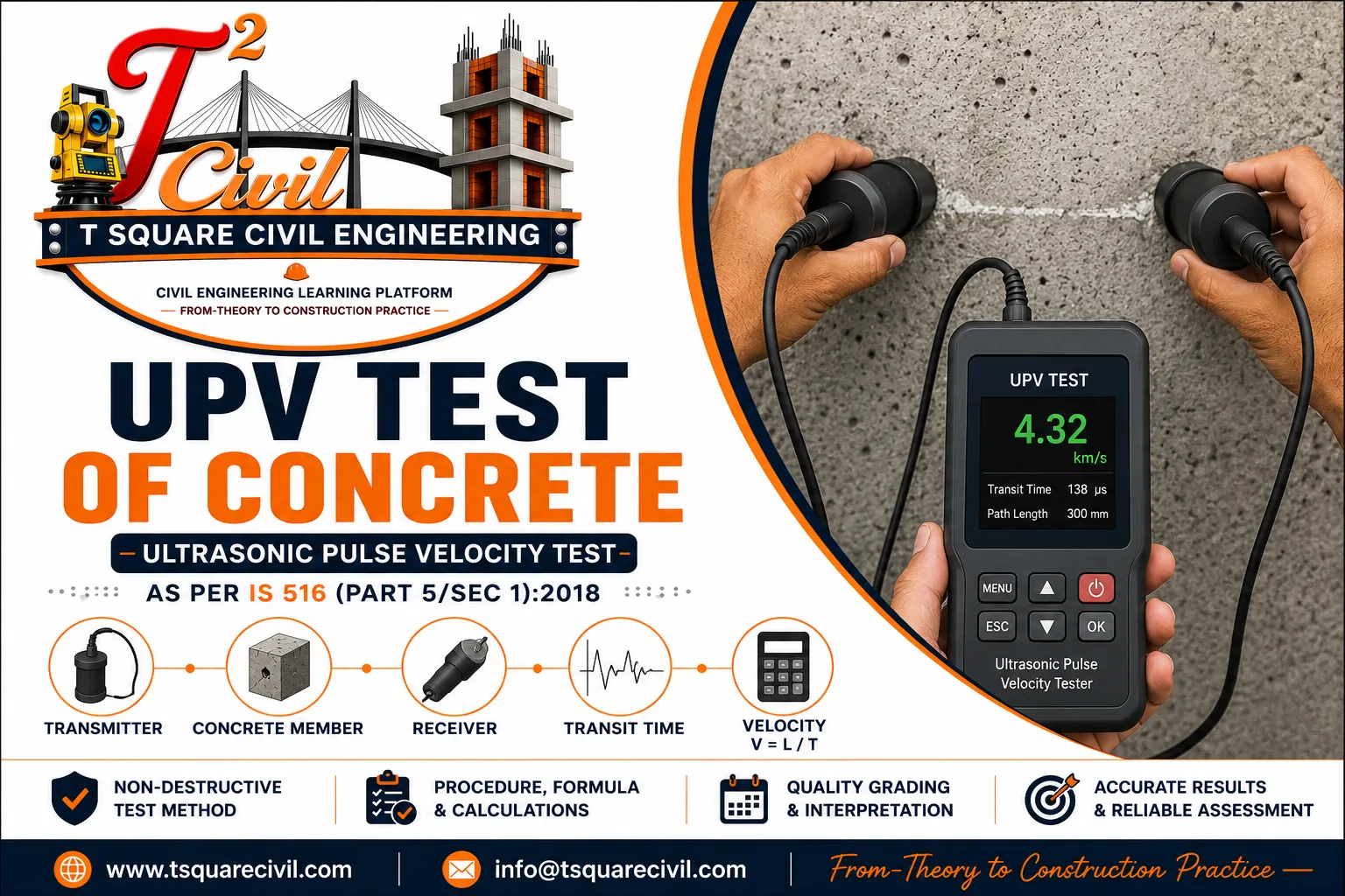
The Ultrasonic Pulse Velocity (UPV) Test is a non-destructive test used to assess the quality and uniformity of hardened concrete by measuring the time taken by an ultrasonic pulse to travel through the concrete.
The pulse velocity is calculated using: V = L / T
Where:
- V = pulse velocity
- L = path length travelled by the pulse
- T = transit time
The test is useful for assessing the uniformity and relative quality of concrete, identifying areas that may contain discontinuities such as cracks or voids, and supporting investigations of existing concrete structures.
The relevant Indian Standard is IS 516 (Part 5/Sec 1):2018, which covers ultrasonic pulse velocity testing as a non-destructive test of hardened concrete.
Important: UPV should not be treated as a standalone method for determining the exact compressive strength of concrete unless an appropriate correlation has been established for the particular concrete and testing conditions.
Quick Answer
The Ultrasonic Pulse Velocity (UPV) Test is a non-destructive test used to assess the quality and uniformity of hardened concrete by measuring the travel time of an ultrasonic pulse through a known path length. The basic formula is V = L/T.
IS Code: IS 516 (Part 5/Sec 1):2018
Test type: Non-destructive
Main result: Pulse velocity
Quick Information Table
| Parameter | Details |
|---|---|
| Test name | Ultrasonic Pulse Velocity Test |
| Common abbreviation | UPV Test |
| Type | Non-destructive test |
| Material | Hardened concrete |
| Main purpose | Assess concrete quality and uniformity |
| Basic measurement | Pulse transit time |
| Basic formula | V = L/T |
| Unit of velocity | km/s or m/s |
| Main equipment | UPV instrument with transmitting and receiving transducers |
| Applicable standard | IS 516 (Part 5/Sec 1):2018 |
| Test category | Non-destructive testing |
| Major applications | Existing structures, uniformity assessment, discontinuity investigation |
BIS identifies IS 516 (Part 5/Sec 1):2018 as the standard for Ultrasonic Pulse Velocity Testing under Part 5, Non-destructive Testing of Concrete.
What Is the Ultrasonic Pulse Velocity Test?
The Ultrasonic Pulse Velocity Test is a non-destructive testing method in which an ultrasonic pulse is transmitted through concrete from one transducer to another.
The instrument measures the time required for the pulse to travel through a known path length.
The velocity is then calculated from: V = L / T
A change in pulse velocity can provide useful information about the uniformity and relative quality of concrete.
The method is particularly useful when engineers need to investigate an existing structure without damaging the concrete.
Why Is the UPV Test Performed?
The test can be used for several purposes, including:
- assessing the uniformity of concrete
- identifying potentially defective zones
- locating areas requiring further investigation
- detecting discontinuities
- investigating cracks and voids
- comparing different portions of a structure
- assessing existing concrete
- supporting structural-condition investigations
- monitoring changes in concrete condition where appropriate
The UPV test is therefore particularly valuable for existing buildings, bridges, foundations, columns, beams, slabs and other concrete structures.
Principle of UPV Test
The basic principle is simple.
An ultrasonic pulse is introduced into the concrete using a transmitting transducer.
The pulse travels through the concrete and is received by another transducer.
The instrument measures:
Transit time of the pulse
If the distance between the transducers is known, pulse velocity can be calculated.
Formula
V = L / T
Where:
V = pulse velocity
L = distance travelled by ultrasonic pulse
T = measured transit time
Apparatus Required
A typical UPV testing system consists of:
- UPV testing instrument
- Transmitting transducer
- Receiving transducer
- Connecting cables
- Couplant
- Measuring arrangement for determining path length
- Suitable accessories required by the equipment manufacturer
The transducers are placed against the concrete surface so that ultrasonic energy can be transmitted into and received from the concrete.
Transmitting and Receiving Transducers
The UPV equipment uses two transducers:
Transmitting transducer
It introduces the ultrasonic pulse into the concrete.
Receiving transducer
It detects the pulse after it has travelled through the concrete.
The instrument determines the transit time between transmission and reception.
Couplant Used in UPV Testing
Good contact between the transducer and concrete surface is important.
A suitable coupling medium is applied between the transducer and the concrete surface to improve transmission of ultrasonic energy.
Poor contact can affect the measured transit time and consequently the calculated velocity.
Therefore:
The concrete surface and transducer contact should be prepared carefully before measurement.
Test Arrangement
The transducers can be positioned in different arrangements depending on the structural element and purpose of testing.
Common arrangements include:
Direct transmission
The transmitting and receiving transducers are placed on opposite faces of the concrete member.
Semi-direct transmission
The transducers are placed on adjacent surfaces.
Indirect or surface transmission
Both transducers are placed on the same surface.
The selected arrangement affects the interpretation of the results and should be carried out in accordance with the applicable standard and testing requirements.
Direct Transmission Method
The direct arrangement is generally advantageous when opposite faces of the concrete member are accessible.
For example:
- opposite faces of a wall
- opposite faces of a suitable specimen
- accessible sides of a structural element
The ultrasonic pulse travels through a relatively well-defined path.
Semi-Direct Transmission
In some structural elements, opposite faces cannot be accessed.
In such cases, the transducers may be positioned on adjacent surfaces.
The path length must be determined appropriately.
Indirect Transmission
When only one concrete surface is accessible, both transducers may be placed on the same surface.
This arrangement can be useful for:
- large slabs
- accessible surfaces of walls
- certain existing structures
However, interpretation should account for the characteristics of the test arrangement and surface condition.
How to Select UPV Test Arrangement
| Transmission method | Transducer position | Typical use |
|---|---|---|
| Direct | Opposite faces | Preferred where both opposite surfaces are accessible |
| Semi-direct | Adjacent faces | Used where opposite faces cannot be accessed |
| Indirect | Same surface | Used where only one surface is accessible |
For comparable measurements, the same transmission arrangement and test conditions should be maintained as far as practicable.
UPV Test Procedure
A typical UPV testing procedure consists of the following steps.
Step 1 — Select the test location
Select representative locations on the concrete member.
Avoid choosing locations without considering:
- cracks
- reinforcement
- surface defects
- accessibility
- structural geometry
The test locations should be selected based on the purpose of the investigation.
Step 2 — Prepare the surface
The surface should be reasonably clean and suitable for proper transducer contact.
Remove loose material or surface contaminants where necessary.
Step 3 — Measure the path length
Determine the distance between the transmitting and receiving points.
Accurate measurement of path length is essential because it directly affects the calculated velocity.
Step 4 — Apply coupling medium
Apply a suitable couplant between the transducer and concrete surface.
This helps provide effective acoustic contact.
Step 5 — Position the transducers
Place the transmitting and receiving transducers in the selected arrangement.
Maintain proper contact with the concrete surface.
Step 6 — Operate the UPV instrument
Generate the ultrasonic pulse and allow the receiving transducer to detect the transmitted signal.
The instrument records the transit time.
Step 7 — Record the reading
Record:
- test location
- path length
- transit time
- transmission arrangement
- calculated pulse velocity
- relevant observations
Step 8 — Calculate pulse velocity
Use: V = L / T
Step 9 — Compare and interpret
Compare readings between different locations and assess the uniformity or potential anomalies.
Interpretation should be based on the applicable standard and the circumstances of the structure being investigated.
UPV Test Formula
The fundamental formula is: V = L / T
Where:
- V = pulse velocity
- L = path length
- T = transit time
Path length = 500 mm
Transit time = 100 μs
V = L / T
V = 500 / 100
V = 5 mm/μs
Therefore:
UPV = 5.0 km/s
This is a simple illustrative calculation. Actual testing and interpretation must follow the applicable standard and test conditions.
UPV Calculation Example
Example 1 — Basic UPV Calculation
Given:
- Path length = 500 mm
- Transit time = 100 μs
Using:
V = L/T
V = 500 / 100
V = 5 mm/μs
Since:
1 mm/μs = 1 km/s
Therefore:
UPV = 5.0 km/s
Example 2 — UPV from a 300 mm Path
Given:
- Path length = 300 mm
- Transit time = 75 μs
Convert:
300 mm = 0.300 m
75 μs = 75 × 10⁻⁶ s
Therefore:
V = L/T
V = 0.300 / (75 × 10⁻⁶)
V = 4000 m/s
Therefore:
UPV = 4.0 km/s
Example 3 — Calculate Transit Time
Given:
- Path length = 600 mm
- UPV = 4.5 km/s
Convert:
600 mm = 0.6 m
4.5 km/s = 4500 m/s
Using:
T = L/V
Therefore:
T = 0.6 / 4500
T = 0.0001333 s
Since:
1 s = 1,000,000 μs
Therefore:
T ≈ 133.3 μs
Example 4 — Compare Two Concrete Locations
Example
Two columns are tested using the same test arrangement.
| Location | Path Length | Transit Time | UPV |
|---|---|---|---|
| Column A | 500 mm | 111 μs | 4.50 km/s |
| Column B | 500 mm | 143 μs | 3.50 km/s |
For Column A: V=500/111≈4.50km/s
For Column B: V=500/143≈3.50km/s
Interpretation
Column B has a significantly lower pulse velocity than Column A.
This does not automatically mean Column B is unsafe or unacceptable.
It means Column B should be considered for further investigation in conjunction with:
- visual inspection
- reinforcement information
- concrete history
- other NDT results
- core testing where required
Example 5 — Quality Grading Example
Example
Suppose the concrete grade is M25 and the average cross-probing UPV is: V=4.20km/s
According to the applicable quality-grading criteria:
4.20 km/s → Good quality grading
But state clearly:
This quality grading does not by itself establish that the concrete has achieved the specified characteristic compressive strength.
Example 6 — Convert UPV from m/s to km/s
Suppose:
UPV = 4200 m/s
Since:
1 km = 1000 m
Therefore:
UPV = 4200/1000
UPV = 4.2 km/s
So:
4200 m/s = 4.2 km/s
UPV Test Results
The result of the test is normally expressed as pulse velocity.
The result should not be interpreted in isolation.
Pulse velocity can be influenced by several factors, including:
- concrete composition
- moisture condition
- temperature
- path length
- reinforcement
- cracks
- voids
- aggregate characteristics
- surface condition
- testing arrangement
Therefore, two concrete locations with different pulse velocities require engineering interpretation rather than an automatic conclusion that one location has a particular compressive strength.
What Does High UPV Indicate?
A relatively high and consistent pulse velocity generally indicates that the ultrasonic pulse is travelling through a comparatively continuous and uniform concrete medium.
However:
A high UPV value alone should not be interpreted as proof of a specific compressive strength.
The result should be considered along with:
- concrete age
- mix characteristics
- moisture condition
- structural history
- other test results
- visual inspection
What Does Low UPV value Indicate?
A relatively low pulse velocity compared with surrounding or comparable locations may indicate the need for further investigation.
Possible causes can include:
- cracks
- voids
- honeycombing
- discontinuities
- poor-quality concrete
- changes in material characteristics
But a low reading does not automatically identify one specific defect.
UPV and Concrete Quality
UPV is particularly useful for comparative assessment.
For example, suppose several columns are tested:
| Location | UPV |
|---|---|
| Column C1 | 4.55 km/s |
| Column C2 | 4.49 km/s |
| Column C3 | 4.52 km/s |
| Column C4 | 3.25 km/s |
Column C4 is noticeably different from the other readings.
This does not by itself prove that C4 is defective.
Instead:
C4 should be identified as a location requiring further investigation.
Example-UPV Test Record
| Location | Path Length | Transit Time | UPV | Observation |
|---|---|---|---|---|
| C1 | 500 mm | 111 μs | 4.50 km/s | Uniform |
| C2 | 500 mm | 112 μs | 4.46 km/s | Uniform |
| C3 | 500 mm | 140 μs | 3.57 km/s | Investigate |
| C4 | 500 mm | 110 μs | 4.55 km/s | Uniform |
C3 shows a comparatively lower velocity and should be considered for further investigation. The result should be interpreted with the concrete grade, transmission arrangement, reinforcement, moisture condition and other available information.
UPV Quality Grading Based on Average Pulse Velocity
The Ultrasonic Pulse Velocity test is primarily used to assess the quality, uniformity and possible internal discontinuities of concrete. UPV results should not be used by themselves as a direct acceptance or rejection criterion for the specified compressive strength of concrete.
As per IS 516 (Part 5/Sec 1):2018, as amended in November 2019, the quality grading is based on the average value of pulse velocity obtained by cross probing.
| Concrete strength | Average pulse velocity by cross probing | Quality grading |
|---|---|---|
| ≤ M25 | Below 3.5 km/s | Doubtful* |
| ≤ M25 | 3.5–4.5 km/s | Good |
| ≤ M25 | Above 4.5 km/s | Excellent |
| > M25 | Below 3.75 km/s | Doubtful* |
| > M25 | 3.75–4.50 km/s | Good |
| > M25 | Above 4.50 km/s | Excellent |
Note: These criteria are for quality grading based on average pulse velocity by cross probing and should not be interpreted as universal acceptance limits for every transmission arrangement or as direct compressive-strength criteria.
* In case of doubtful quality, additional tests should be carried out.
These criteria are for concrete quality grading, not for directly determining the compressive-strength grade of concrete. The 2019 amendment to IS 516 (Part 5/Sec 1):2018 specifically revised the velocity criteria according to whether the concrete strength is ≤ M25 or > M25.
UPV Test vs Compressive Strength
- UPV measures pulse velocity.
- Compressive strength is determined through strength testing.
- UPV can be correlated with strength only when an appropriate relationship has been established.
- The relationship depends on the concrete and testing conditions.
- A generic equation should not be applied to every concrete.
Example: A UPV of 4.2 km/s should not simply be converted into “M30 concrete” without an appropriate validated correlation.
Important: UPV Quality Grading Is Not Compressive-Strength Acceptance
A UPV result should not be interpreted as meaning that a concrete member automatically satisfies its specified characteristic compressive strength.
For example, a UPV result classified as “Good” does not mean that the concrete has automatically achieved M25, M30, M35 or any other particular strength grade.
UPV is affected by factors such as:
- concrete composition
- aggregate type
- moisture condition
- temperature
- reinforcement
- cracks
- voids
- honeycombing
- path length
- transmission arrangement
- surface condition
Therefore, the UPV result should be interpreted together with the structural condition and other available test information.
What if the UPV result is doubtful?
If the average pulse velocity falls within the doubtful category, additional investigation should be carried out rather than immediately rejecting the concrete.
Depending on the purpose of the investigation, additional testing may include:
- visual inspection
- additional UPV measurements
- rebound hammer testing
- core testing
- review of reinforcement arrangement
- review of construction records
- comparison with other test locations
Can UPV determine compressive strength?
UPV does not directly determine compressive strength.
If an estimate of compressive strength from UPV is required, an appropriate correlation should be established using concrete made with the same or suitably representative materials and mix proportions and under comparable conditions.
Therefore:
UPV quality grading and compressive-strength acceptance are two different assessments.
What should be done when UPV is low?
If a location produces an unusually low UPV compared with surrounding locations, it should be identified for further investigation rather than automatically being rejected.
Further investigation may include:
- visual inspection
- additional UPV measurements
- rebound hammer testing
- core testing where required
- review of reinforcement arrangement
- review of concrete records
- comparison with other test locations
Important distinction
UPV acceptance ≠ compressive-strength acceptance.
The UPV test does not directly establish whether concrete has achieved its specified characteristic compressive strength. If compressive strength needs to be established, appropriate strength testing and/or a properly established correlation should be used.
For site quality control, the acceptance of concrete should ultimately be based on the applicable project specification and the relevant provisions of the governing IS Code, not on a generic UPV table alone.
Factors Affecting UPV Results
1 Moisture Condition
The moisture condition of concrete can affect pulse transmission.
Therefore, the testing condition should be recorded and considered during interpretation.
2 Aggregate Type
Concrete containing different aggregates can produce different pulse velocities.
Therefore, direct comparison between fundamentally different concrete compositions should be made cautiously.
3 Reinforcement
Steel reinforcement can influence the ultrasonic pulse path.
The location and orientation of reinforcement should therefore be considered when interpreting results.
4 Cracks
Cracks can interrupt or alter the pulse path.
Consequently, the measured transit time can differ from that of relatively continuous concrete.
5 Voids and Honeycombing
Internal voids and honeycombing can influence pulse transmission and may result in anomalous readings.
For this reason, UPV can be useful during investigation of suspected defective concrete.
6 Surface Condition
Poor transducer contact or an unsuitable surface can affect the measurement.
Proper surface preparation and coupling are therefore important.
Advantages of UPV Test
The major advantages include:
- non-destructive
- rapid testing
- useful for existing structures
- can assess large areas
- can identify locations requiring investigation
- useful for comparing different concrete zones
- minimal physical damage
- useful alongside other NDT methods
Limitations of UPV Test
UPV also has limitations.
It should not be treated as a universal substitute for destructive testing.
Important limitations include:
- results depend on testing conditions
- reinforcement can affect measurements
- moisture affects readings
- aggregate characteristics influence pulse velocity
- cracks can affect the pulse path
- surface condition affects coupling
- exact compressive strength cannot simply be obtained from UPV without a suitable established correlation
For structural assessment, the engineer should consider the UPV results together with other available information.
UPV Test vs Rebound Hammer Test
Both are non-destructive tests, but they provide different information.
| Parameter | UPV Test | Rebound Hammer |
|---|---|---|
| Main measurement | Pulse velocity | Surface rebound |
| Type | NDT | NDT |
| Main use | Quality/uniformity investigation | Surface hardness/relative assessment |
| Equipment | UPV instrument | Rebound hammer |
| Internal discontinuity assessment | Can help identify anomalous zones | Primarily surface-related |
| Surface condition | Important | Important |
| Reinforcement influence | Important | Can also affect readings |
| Standalone compressive strength | Not directly | Not directly |
| Best use | Often complementary | Often complementary |
UPV Test and Rebound Hammer — Combined Assessment
UPV and rebound hammer testing can provide complementary information during concrete investigations. UPV primarily evaluates ultrasonic pulse transmission through concrete, while rebound hammer testing provides information related to surface hardness.
Where both methods are used, the results should be interpreted together with the condition of the structure and other available evidence.
Any estimation of compressive strength using combined NDT results should be based on an appropriate correlation established for the concrete under investigation.
UPV Test vs Core Test
| Parameter | UPV Test | Core Test |
|---|---|---|
| Type | Non-destructive | Partially destructive |
| Damage | Minimal | Requires extraction of concrete core |
| Main purpose | Quality/uniformity investigation | Direct testing of extracted concrete |
| Speed | Rapid | More time-consuming |
| Structural damage | Minimal | Localized damage |
| Strength determination | Not direct | Can directly test extracted core |
| Best use | Screening/investigation | Detailed strength investigation |
UPV and core testing should not be considered interchangeable. In an investigation, UPV may help identify areas requiring more detailed examination, while core testing can provide direct information from extracted concrete.
UPV vs Rebound Hammer vs Core Test
| Test | NDT? | Main information | Damage |
|---|---|---|---|
| UPV | Yes | Pulse velocity / uniformity | Minimal |
| Rebound Hammer | Yes | Surface hardness / relative assessment | Minimal |
| Core Test | No | Properties of extracted concrete | Localized |
In structural investigations, these methods can be complementary rather than mutually exclusive.
UPV Test Applications in Civil Engineering
UPV can be useful for investigating:
Buildings
- columns
- beams
- slabs
- walls
Bridges
- deck elements
- piers
- structural members
Foundations
- accessible concrete elements
Existing structures
- condition investigations
- suspected defective zones
- comparative assessment
Quality investigations
- suspected honeycombing
- suspected cracks
- unusual concrete zones
UPV Test on Beam, Column, Slab and Wall
UPV Test on Columns
UPV testing can be carried out at selected locations on accessible column surfaces to compare the relative uniformity of concrete. Reinforcement arrangement, surface condition and the selected transmission path should be considered when interpreting the readings.
UPV Test on Beams
For beams, the transmission arrangement should be selected according to the accessible faces and the purpose of the investigation. Where comparable locations are being assessed, consistent test conditions should be maintained as far as practicable.
UPV Test on Slabs
Where only one surface of a slab is accessible, indirect transmission may be considered. The limitations associated with the selected transmission arrangement and surface condition should be taken into account during interpretation.
UPV Test on Walls
Where opposite faces of a wall are accessible, direct transmission can provide a defined pulse path. The path length, transmission arrangement and test location should be recorded in the test report.
Note: The actual test arrangement should be selected according to structural geometry, accessibility, test purpose and the applicable testing standard.
Practical Site Example: Investigating Suspected Honeycombing
Suppose honeycombing is visually suspected in a column.
Step 1
Carry out visual inspection.
Step 2
Select several comparable locations.
Step 3
Carry out UPV measurements using an appropriate transmission arrangement.
Step 4
Compare the readings.
Step 5
Identify significantly anomalous locations.
Step 6
If required, carry out additional investigation such as rebound hammer testing or core testing.
Conclusion
UPV can help identify areas that deserve further investigation, but the UPV result alone should not be used to declare the column structurally unsafe.
Common Mistakes During UPV Testing
Mistake 1 — Poor transducer contact
This can affect the measured transit time.
Mistake 2 — Ignoring reinforcement
Steel can influence the pulse path.
Mistake 3 — Comparing different concrete types directly
Concrete composition affects pulse velocity.
Mistake 4 — Ignoring moisture condition
Moisture can influence the reading.
Mistake 5 — Treating one reading as conclusive
A single anomalous result should generally trigger further investigation rather than an immediate structural conclusion.
Mistake 6 — Converting UPV directly into compressive strength
This is one of the most important mistakes to avoid.
A reliable strength relationship requires appropriate calibration/correlation.
UPV Test Report Format
A practical test report should record information such as:
| Item | Details |
|---|---|
| Project | Project name |
| Structure | Building/bridge/etc. |
| Member | Beam/column/slab/wall |
| Location | Grid/location |
| Date | Test date |
| Concrete age | Age at testing |
| Surface condition | Relevant observation |
| Moisture condition | Relevant observation |
| Transmission arrangement | Direct/semi-direct/indirect |
| Path length | Measured length |
| Transit time | Instrument reading |
| Pulse velocity | Calculated value |
| Remarks | Engineering observations |
How to Interpret a UPV Test Report
Suppose the report shows:
Location: C3
Path length: 500 mm
Transit time: 140 μs
UPV: 3.57 km/s
Transmission: Direct
The engineer should not conclude simply:
“C3 has low strength.”
Instead:
“C3 has a comparatively lower UPV and should be reviewed in the context of the concrete grade, transmission arrangement, reinforcement, moisture condition and other investigation results.”
IS Code for UPV Test
The relevant Indian Standard is:
IS 516 (Part 5/Sec 1):2018
Hardened Concrete — Methods of Test: Part 5 Non-destructive Testing of Concrete: Section 1 Ultrasonic Pulse Velocity Testing (First Revision).
BIS lists this standard under the IS 516 series and identifies it specifically as the standard covering ultrasonic pulse velocity testing.
The BIS standards portal also provides access to standard information through its Know Your Standard service.
Important: For detailed numerical requirements and testing procedures, the engineer/testing laboratory should consult the current official standard rather than relying on a secondary website summary.
UPV Test — Quick Revision
Remember these five points:
1. UPV is a non-destructive test.
2. It measures ultrasonic pulse transit time through concrete.
3. Basic formula: V=L/T
4. It is useful for assessing uniformity and identifying areas requiring further investigation.
5. UPV should not automatically be converted into compressive strength without an appropriate correlation.
Viva Questions and Answers
Q1. What is UPV?
UPV stands for Ultrasonic Pulse Velocity.
Q2. Is UPV destructive?
No. It is a non-destructive test.
Q3. What does UPV measure?
It measures the velocity of an ultrasonic pulse travelling through concrete.
Q4. What is the formula for UPV?
V=L/T
Q5. What is the relevant IS Code?
IS 516 (Part 5/Sec 1):2018.
Q6. What are the two main transducers?
A transmitting transducer and a receiving transducer.
Q7. Why is coupling medium used?
To improve contact and transmission of ultrasonic energy between the transducer and concrete.
Q8. Can UPV directly determine compressive strength?
No. A suitable correlation is required for strength estimation.
Q9. What is the acceptable UPV value for concrete?
There is no single UPV value that universally establishes acceptance of concrete for every project. Under IS 516 (Part 5/Sec 1):2018, as amended in 2019, average pulse velocity by cross probing is used for concrete quality grading, with different criteria for concrete of ≤ M25 and > M25. Values classified as doubtful require additional investigation. UPV quality grading should not be treated as a direct determination of compressive strength.
Exam Questions and Answers
Q1. UPV is mainly used for:
Answer: Non-destructive assessment of concrete quality/uniformity.
Q2. The basic UPV equation is:
Answer: V=L/T
Q3. UPV is expressed in:
Answer: Commonly m/s or km/s.
Q4. What standard covers ultrasonic pulse velocity testing of hardened concrete in India?
Answer: IS 516 (Part 5/Sec 1):2018.
Q5. Name two common UPV transmission arrangements.
Answer: Direct and indirect transmission; semi-direct transmission is also used.
Interview Questions and Answers
Q1. Why would you use UPV on an existing building?
To investigate concrete uniformity and identify locations that may require further examination without significantly damaging the structure.
Q2. Why should reinforcement be considered?
Reinforcement can influence the ultrasonic pulse path and therefore affect the measured result.
Q3. Why should moisture condition be recorded?
Concrete moisture condition can influence ultrasonic pulse transmission and consequently the measured velocity.
Q4. Can UPV replace a core test?
Not automatically. The appropriate investigation method depends on the purpose, structure and engineering assessment.
Q5. What would you do if one column shows a significantly lower UPV than surrounding columns?
Treat it as a location requiring further investigation and correlate it with visual inspection and, where appropriate, other tests.
Frequently Asked Questions
What is the UPV test of concrete?
It is a non-destructive test that measures the travel velocity of an ultrasonic pulse through concrete.
What is the formula for UPV?
V=L/T
where L is the pulse path length and T is transit time.
Which IS Code is used for UPV?
IS 516 (Part 5/Sec 1):2018 covers ultrasonic pulse velocity testing of hardened concrete.
Is UPV a destructive test?
No. It is a non-destructive test.
Can UPV detect cracks?
UPV measurements can help identify anomalous zones associated with discontinuities, but the results require engineering interpretation.
Can UPV determine concrete compressive strength?
Not directly. A suitable correlation must be established for the concrete and testing conditions if strength estimation is required.
Is UPV better than rebound hammer?
Neither is universally “better.” They provide different information and can be used as complementary NDT methods.
Why is coupling medium used?
To improve acoustic contact between the transducer and concrete surface.
Does reinforcement affect UPV?
Yes. Reinforcement can influence the pulse path and should be considered during interpretation.
Can UPV be used on existing structures?
Yes. It is particularly useful for non-destructive investigation of existing concrete structures.
What is a good UPV value for concrete?
A good Ultrasonic Pulse Velocity (UPV) value depends on the concrete strength category and the applicable quality-grading criteria. As per IS 516 (Part 5/Sec 1):2018, as amended in 2019, the quality grading based on average pulse velocity obtained by cross probing is:
- For concrete ≤ M25, a pulse velocity of 3.5–4.5 km/s is graded as Good, while a value above 4.5 km/s is graded as Excellent.
- For concrete > M25, a pulse velocity of 3.75–4.50 km/s is graded as Good, while a value above 4.50 km/s is graded as Excellent.
UPV quality grading should not be treated as a direct measure of compressive strength or as a universal acceptance criterion for concrete. Test arrangement, moisture condition, reinforcement, concrete composition and other relevant factors should also be considered when interpreting the results.
What is the UPV value for M25 concrete?
For M25 concrete, the quality-grading criteria applicable to concrete of ≤ M25 can be used for assessment based on average pulse velocity obtained by cross probing.
- Below 3.5 km/s — Doubtful
- 3.5–4.5 km/s — Good
- Above 4.5 km/s — Excellent
If the UPV falls in the doubtful range, additional investigation should be carried out.
A UPV value should not be used by itself to conclude that concrete has achieved the specified M25 compressive strength. UPV quality grading and compressive-strength acceptance are different assessments.
Can UPV detect honeycombing in concrete?
UPV testing can help identify anomalous zones that may be associated with honeycombing, voids or other discontinuities in concrete. Areas containing discontinuities may produce pulse velocities that differ from those obtained in surrounding or comparable concrete.
However, a low or abnormal UPV reading does not by itself prove that honeycombing is present. The result should be interpreted together with visual inspection, reinforcement details, concrete history and, where necessary, additional tests such as rebound hammer or core testing.
Therefore, UPV is particularly useful for identifying locations that require further investigation rather than confirming honeycombing solely from a single reading.
Can UPV replace a core test?
No. UPV testing should not automatically be considered a replacement for core testing.
UPV is a non-destructive test primarily used to assess pulse velocity, concrete uniformity and possible anomalous zones. A core test involves extracting concrete from the structure and testing the core specimen directly.
The two methods can therefore serve different purposes during a structural investigation. UPV may help identify areas requiring more detailed examination, while core testing may be used where direct testing of extracted concrete is required.
The appropriate test or combination of tests should be selected according to the purpose of the investigation, structural condition, project requirements and engineering assessment.
What is the difference between direct and indirect UPV testing?
The main difference between direct and indirect UPV testing is the position of the transmitting and receiving transducers.
In direct transmission, the transmitting and receiving transducers are placed on opposite faces of the concrete member. The ultrasonic pulse travels through a relatively well-defined path between the two transducers.
In indirect or surface transmission, both transducers are placed on the same concrete surface. This arrangement can be useful where only one surface of the structural element is accessible.
Where suitable access is available, direct transmission is generally advantageous because the pulse travels through a more clearly defined path. The selected transmission arrangement should always be considered when interpreting and comparing UPV results.
About T Square Civil Engineering
T Square Civil Engineering is a learning platform dedicated to providing accurate, practical, and easy-to-understand civil engineering knowledge. Our mission is to help students, site engineers, and construction professionals bridge the gap between engineering theory and real-world construction practice through detailed guides, calculators, and industry-focused resources.
Continue Your Learning
If you found this guide helpful, explore our other civil engineering resources:
- Rebound Hammer Test of Concrete
- Concrete Cube Compressive Strength Test
- Concrete Cube Casting Procedure
- Concrete Curing Methods
- Flexural Strength Test of Concrete
- Split Tensile Strength Test of Concrete
- Concrete Volume Calculator
- Cement, Sand & Aggregate Calculator
- Steel Weight Calculator
- Slump Test of Concrete
- Standard Consistency Test of Cement
- Initial & Final Setting Time Test
- Concrete Mix Design-M60
- Concrete Technology Interview Questions and Answers
These resources are designed to help students and professionals understand civil engineering concepts through practical examples, calculators, and step-by-step guides.
Disclaimer: The information provided on T Square Civil Engineering is for educational purposes only. While every effort has been made to ensure technical accuracy, readers should verify the latest Indian Standards (IS Codes), project specifications, and applicable regulations before using this information for design, construction, testing, or quality control. T Square Civil Engineering is not responsible for any loss or damage arising from the use of this content.